
Systems and methods for automation of a control knob unit

a technology of control knob and system, applied in the direction of combustion types, fire safety, domestic stoves or ranges, etc., can solve the problems of affecting the normal operation of the business, affecting the safety of the operation, and causing the production of smoke and fir

Inactive Publication Date: 2012-12-27
LEGASPI FERDINAND VILLEGAS +2
View PDF43 Cites 43 Cited by
  • Summary
  • Abstract
  • Description
  • Claims
  • Application Information

AI Technical Summary

Benefits of technology

[0015]According to another feature, the control knob unit may further comprise a motorized locking mechanism. The motorized locking mechanism may comprise a rotating wheel rotatably engaged with the housing...

Problems solved by technology

Many of these residential and commercial fires originate in the kitchen as overheated cooking oils or greases during cooking can easily ignite which result in potentially dangerous fires leading to the production of smoke and fire.
Within minutes of bursting into flames, a fire may consume the contents, walls and ceiling of the room where the fire started and the combination of heat, smoke and carbon monoxide can kill everyone in the area.
Furthermore, in commercial eating establishments, fires from cooking devices can be devastating, often causing cessation of normal business activities for days or weeks, and sometimes permanently.
Due to the nature of cooking, the threat of a fire is always present.
However, if no one is around to hear and / or see the alarm, the fire will continue to burn causing significant damage.
Another possible cause of a fire is the danger of a gas explosion as a result from gas leaking from broken gas pipes following an earthquake.
Sometimes the damage caused by the earthquake may not appear significant, but if the gas accumulates and explodes due to the gas leak, the damage could be catastrophic and life threatening.
However, if no one is around, the appliance or other device cannot be shut off.

Method used


Image

  • Systems and methods for automation of a control knob unit
  • Systems and methods for automation of a control knob unit
  • Systems and methods for automation of a control knob unit

Examples


Embodiment Construction

[0039]The following detailed description is of the best currently contemplated modes of carrying out the invention. The description is not to be taken in a limiting sense, but is made merely for the purpose of illustrating the general principles of the invention. In the following description, specific details are given to provide a thorough understanding of the embodiments. However, it will be understood by one of ordinary skill in the art that the embodiments may be practiced without these specific details. For example, circuits may be shown in block diagrams in order not to obscure the embodiments in unnecessary detail. In other instances, well-known circuits, structures and techniques may not be shown detail in order not to obscure the embodiments.

[0040]Also, it is noted that the embodiments may be described as a process that is depicted as a flowchart, a flow diagram, a structure diagram, or a block diagram. Although a flowchart may describe the operations as a sequential proces...


PUM


Abstract

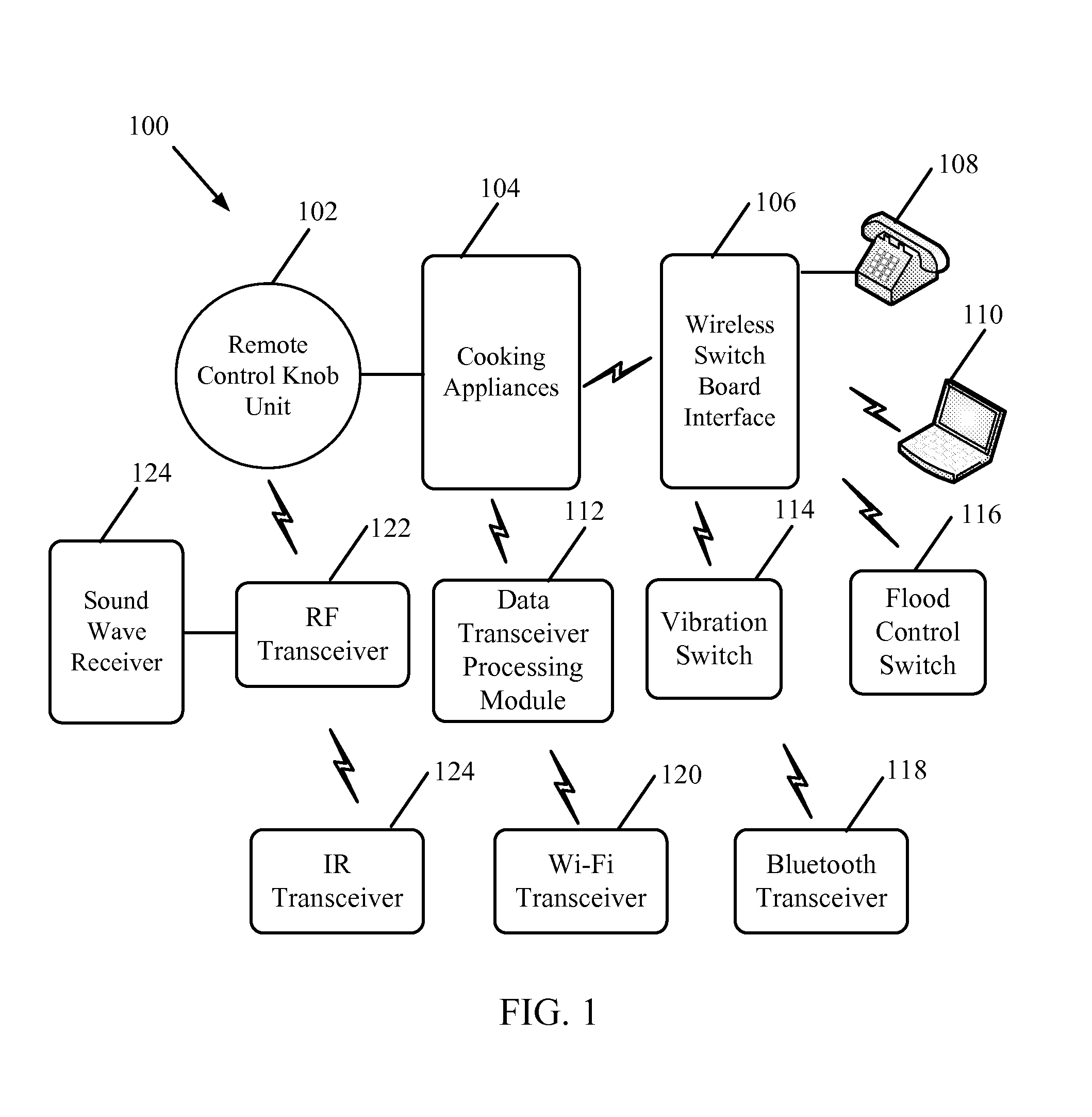
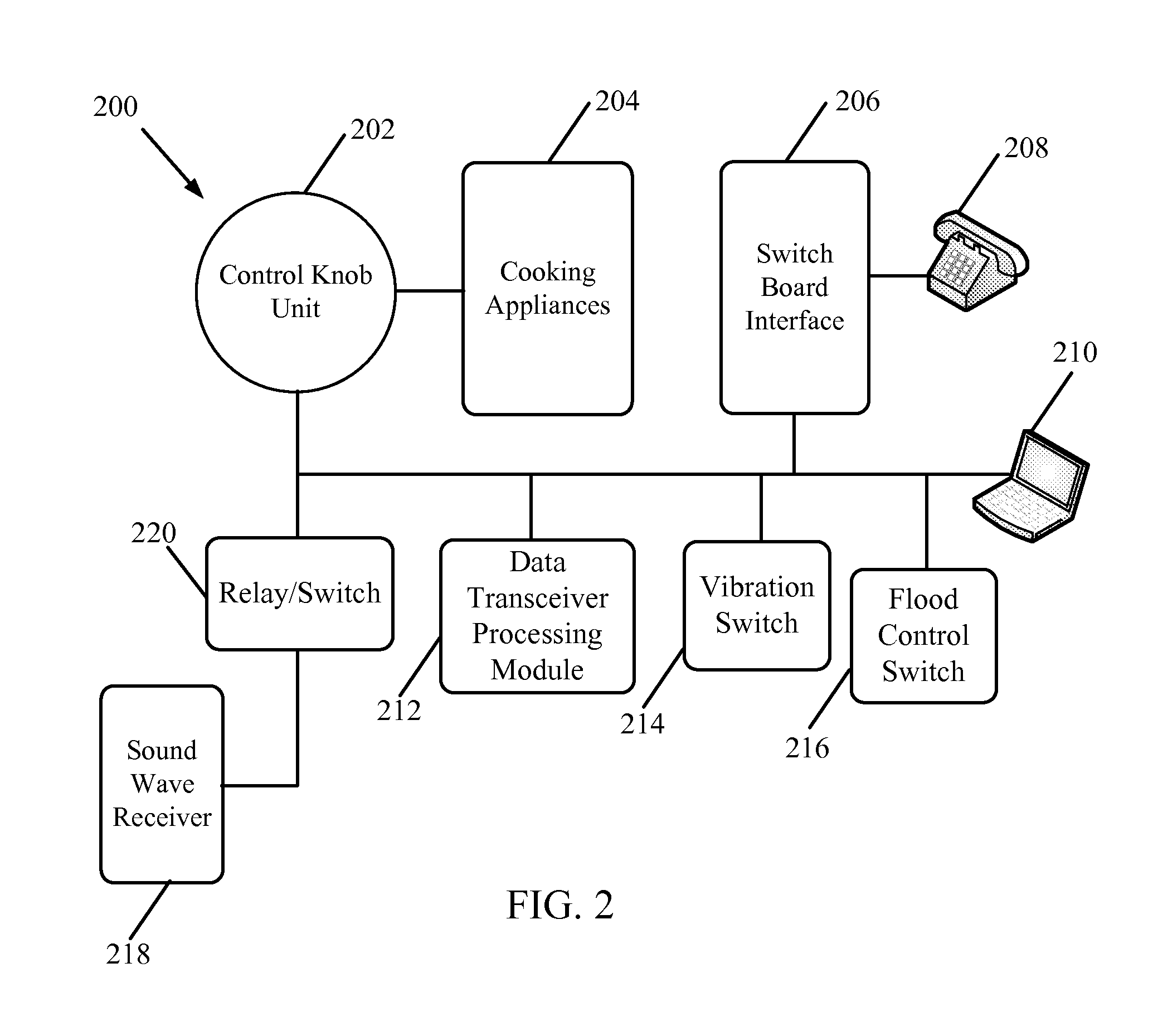
A system and method for automatically rotating a control knob unit on an appliance or other device to an Off position upon the occurrence of a safety event is provided. The control knob unit may be secured to and engaged with an operational shaft on the appliance which controls the flow of gas or power to the appliance. The system may include one or more detectors (or detector modules) that are configured to emit a signal upon an occurrence of the event, such as a fire, which may be an early indication of a developing emergency. The signal may be in the form of an audible alert, such as sound (or sound waves). A data transceiver processing module may receive a plurality of sound waves and analyze the plurality of sound waves for a variation in frequency (or Doppler Effect) to determine if any of the sound waves originate from the one or more detector modules.

Description

CLAIM OF PRIORITY[0001]The present Application for Patent claims priority to U.S. Provisional Application No. 61 / 571,379 entitled “Methods and Automation of Appliances Control Knob”, filed Jun. 27, 2011, and hereby expressly incorporated by reference herein.FIELD[0002]The present invention relates to the field of automated safety capabilities for appliances or other devices, in particular, to systems and methods for automatically positioning a control knob unit to an Off position upon the occurrence of a safety event. Positioning the control knob unit to an Off position causes the gas and / or electricity emanating from the appliances, such as from burners on a stove, to terminate.BACKGROUND OF THE INVENTION[0003]A large number of residential and commercial fires could be prevented if stopped from proliferating during their early stages. Many of these residential and commercial fires originate in the kitchen as overheated cooking oils or greases during cooking can easily ignite which ...

Claims


Application Information

Patent Timeline
IPC IPC(8): F24C3/12F23N5/24F16K17/36
CPCF23N5/242F23N2023/38F23N2035/24F23N2031/20F23N2031/00F23N2223/38F23N2231/00F23N2231/20F23N2235/24F24C7/08Y10T137/1915
Inventor LEGASPI, FERDINAND VILLEGASGALLARDO, JR., PERFECTO FERRERBERNARDO, FERNANDO MEDINA
Owner LEGASPI FERDINAND VILLEGAS
Learn More