Eureka AIR delivers breakthrough ideas for toughest innovation challenges, trusted by R&D personnel around the world.

Method of Reducing Resistance of Streamlined Body of A Vehicle and Its Applications

Inactive Publication Date: 2012-12-27
MEI CHEN HSIN
View PDF6 Cites 1 Cited by
  • Summary
  • Abstract
  • Description
  • Claims
  • Application Information

AI Technical Summary

Benefits of technology

[0008]The major objective of the present invention is to provide a method of reducing resistance of a streamlined body and its applications, wherein at least one raised structure to be installed on the caudal end of the streamlined body so that the fluid pressure on the caudal surface can be increased by means of the raised structure, thereby reducing resistance of which the streamlined body will encounter during movement.
[0009]Another objective of the present invention lies in providing a method of reducing resistance of a streamlined body and its applications, which can be widely applied to various streamlined vehicles such as a vessel, an aircraft or an automobile and the like.
[0010]To successfully achieve the aforementioned goals, the present invention discloses a method of reducing resistance of a streamlined body and its applications, wherein one or more raised structures are configured between the widest point and the caudal end of a streamlined body, and a gap can be configured between such raised structures. By such a method, the raised structure can hinder the boundary layer and guide the fluid to increase pressure on the caudal end of the streamlined body for reducing resistance to which the streamlined body is subject in cruising. The present invention can be comprehensively applied on various streamlined bodies so as to improve their travelling speed.

Problems solved by technology

Such resistance may not only cause the vehicle to consume more energy (e.g., thermal energy or electric energy), but the driving mechanism and transmitting mechanism thereof will also suffer more burden, extra energy loss and time loss.
Consequently, the resistance will produce extra waste gas or heat, causing pollution as well as inefficiency with regard to both energy cost and operation time for transportation companies.
Although a streamlined design can be helpful for reducing resistance, such an approach can actually provide limited effects with regard to resistance reduction.

Method used


Image

  • Method of Reducing Resistance of Streamlined Body of A Vehicle and Its Applications
  • Method of Reducing Resistance of Streamlined Body of A Vehicle and Its Applications
  • Method of Reducing Resistance of Streamlined Body of A Vehicle and Its Applications

Examples


Embodiment Construction

[0024]Other characteristics of the present invention as well as embodiments thereof can be further appreciated through following detailed descriptions in conjunction with the appended drawings.

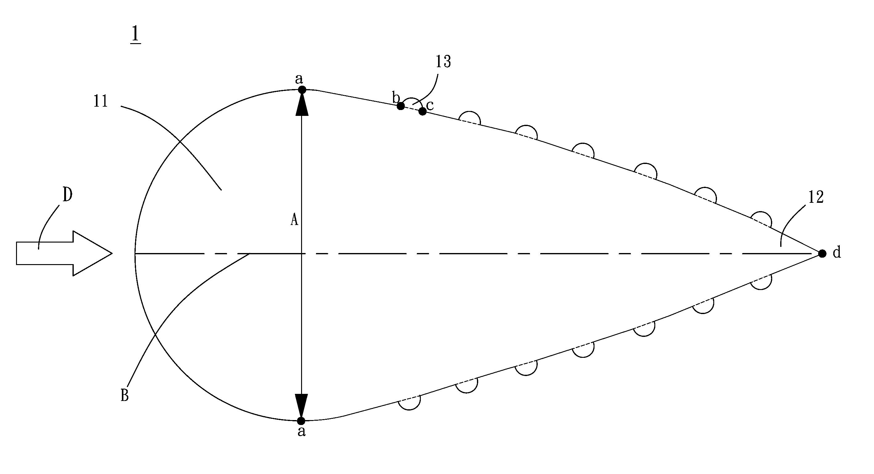
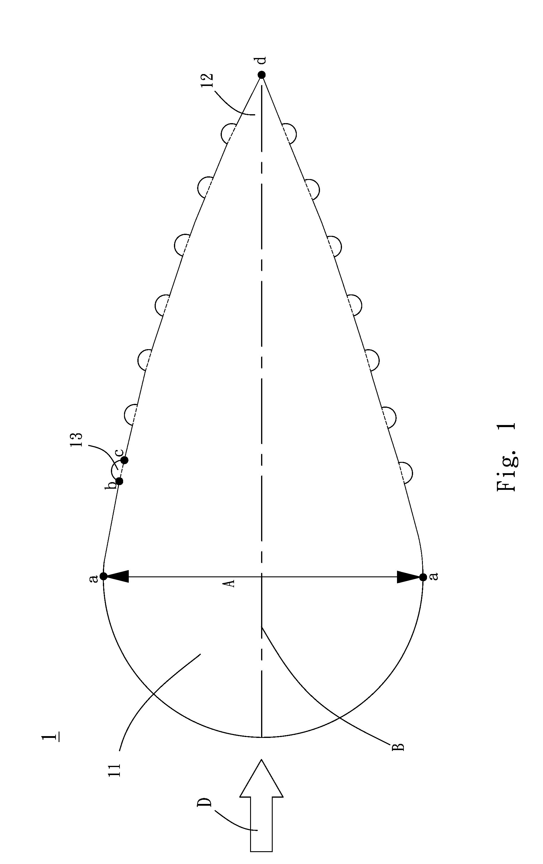
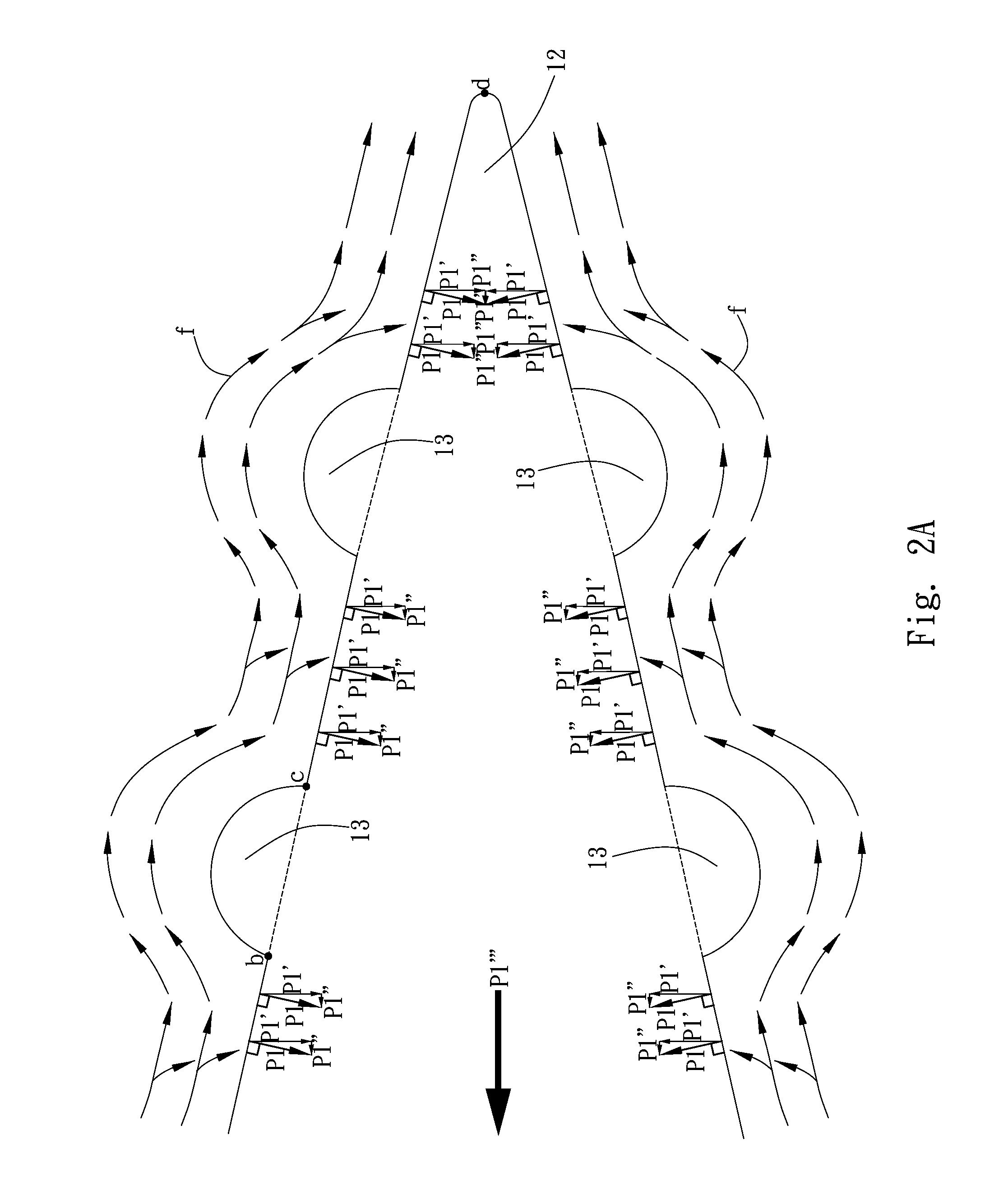
[0025]Refer to FIG. 1, wherein a cross-section view of a streamlined body according to a preferred embodiment of the present invention is shown. The method of reducing resistance of a streamlined body according to the present invention is to install one or more raised structures 13 on the surface between the widest point A and the caudal end 12 of the streamlined body 1; in other word, at least one raised structure 13 is configured between the point a and the point d, and the caudal end 12 of the streamlined body 1 indicates the end position where the fluid passes by the streamlined body 1. In the present embodiment, the flow direction D of the fluid heads toward the right side, so the end position of the streamlined body 1 is the caudal end 12. Herein a gap can be configured between every two...


PUM


Abstract

A method of reducing resistance of streamlined body of a vehicle and its applications is provided, wherein one or more raised structures are configured between the widest point and the caudal end of a streamlined body, and a gap can be configured between such raised structures. In this way, the raised structure can impede and guide the boundary layer of the fluid to exert more pressure on the caudal end of the streamlined body thereby reducing resistance to which the streamlined body may be subject. The present invention can be applied to various streamlined bodies in order to increase the speed of a cruising streamlined body.

Description

BACKGROUND OF THE INVENTION[0001]1. Field of the Invention[0002]The present invention generally relates to a method of reducing resistance of a streamlined body and its applications. Especially, the method refers at least one raised structure configured on a streamlined vehicle for increasing the pressure on its caudal end during its cruising, so that it can facilitate resistance reduction in certain applications thereof.[0003]2. Description of Related Art[0004]One of the major factors that influence the travelling speed of a vehicle is fluid resistance to which it is subject during cruising. Such resistance may not only cause the vehicle to consume more energy (e.g., thermal energy or electric energy), but the driving mechanism and transmitting mechanism thereof will also suffer more burden, extra energy loss and time loss. Consequently, the resistance will produce extra waste gas or heat, causing pollution as well as inefficiency with regard to both energy cost and operation time ...

Claims


Application Information

Patent Timeline
IPC IPC(8): B60R13/00B64C23/00
CPCB63B1/36F15D1/0045Y02T50/166Y02T70/121B64C21/10Y02T50/10Y02T70/10Y10T137/0318B63B1/34B64C21/00F15D1/12
Inventor MEI, CHEN-HSIN
Owner MEI CHEN HSIN
Why Eureka
Eureka Blog
Learn More