Oil cooler

Inactive Publication Date: 2012-12-27
MAHLE FILTER SYST JAPAN CORP
View PDF6 Cites 19 Cited by
  • Summary
  • Abstract
  • Description
  • Claims
  • Application Information

AI Technical Summary

Benefits of technology

[0014]The oil cooler according to the present invention can serve for identifying a specific core plate on the basis of a difference in height of a peripheral wall between a plurality of core plates even after the core plates are stacked on each other. Further, a person who handles the oil cooler according to the present invention can be prevented from suffering an injury due to a configuration of the identifying portion of the core plate. Furthermore, the oil cooler according to the present invention can serve for suppressing reduction in strength of the specific core plate to be identified and deterioration of anticorrosion property.

Problems solved by technology

Therefore, there is a possibility that a person who handles the oil cooler is accidentally injured.
On the other hand, in a case where the recess is formed on the outer circumferential periphery of each of the closing plate and the first plate, there is also a possibility that a person who handles the oil cooler is accidentally injured with a corner edge of the recess.
Due to the thus formed recess, there will occur reduction in strength of the cylindrical wall in a position in which the recess is formed, and deterioration in anticorrosion property.

Method used


Image

  • Oil cooler
  • Oil cooler
  • Oil cooler

Examples


first embodiment

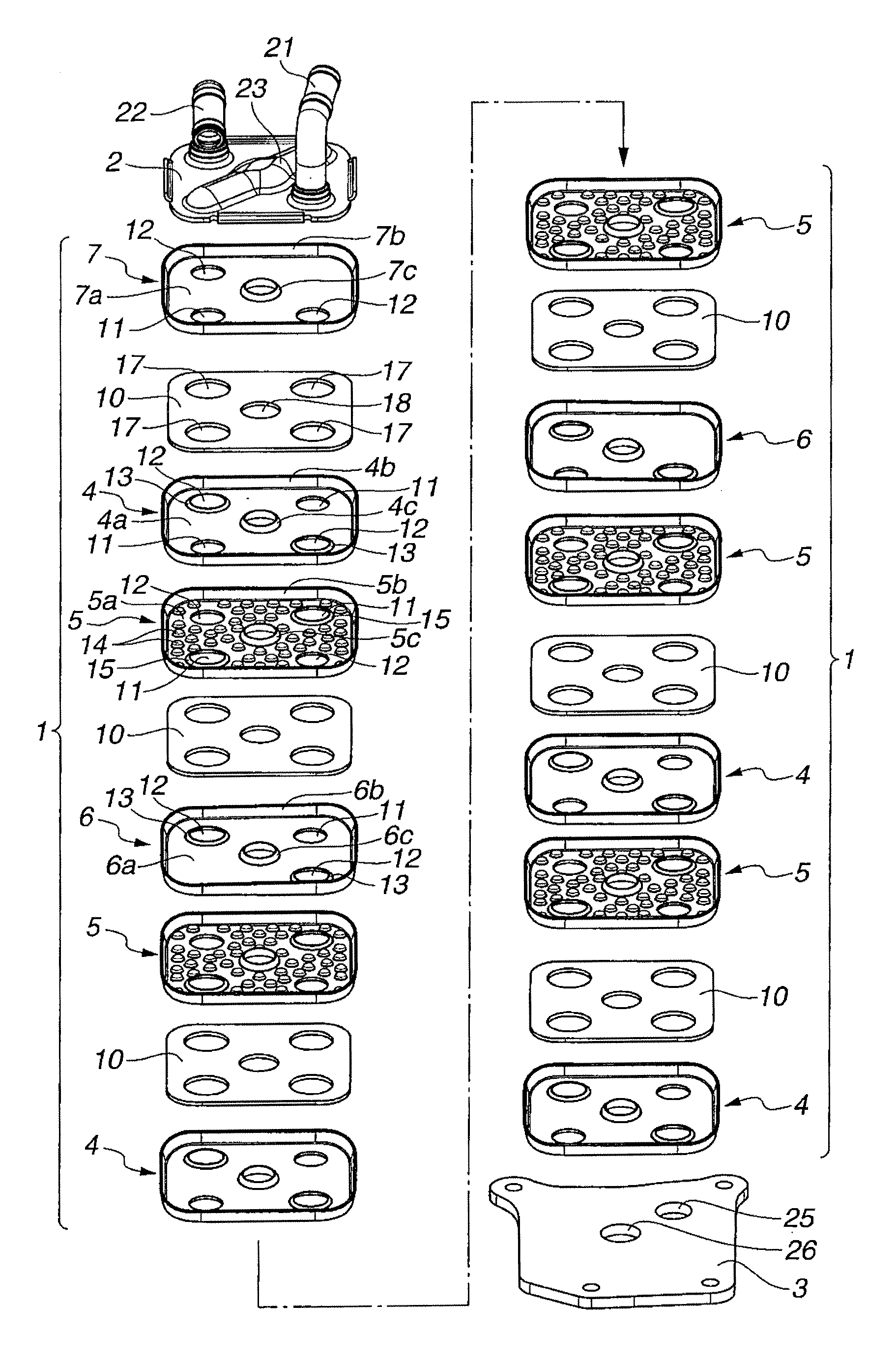
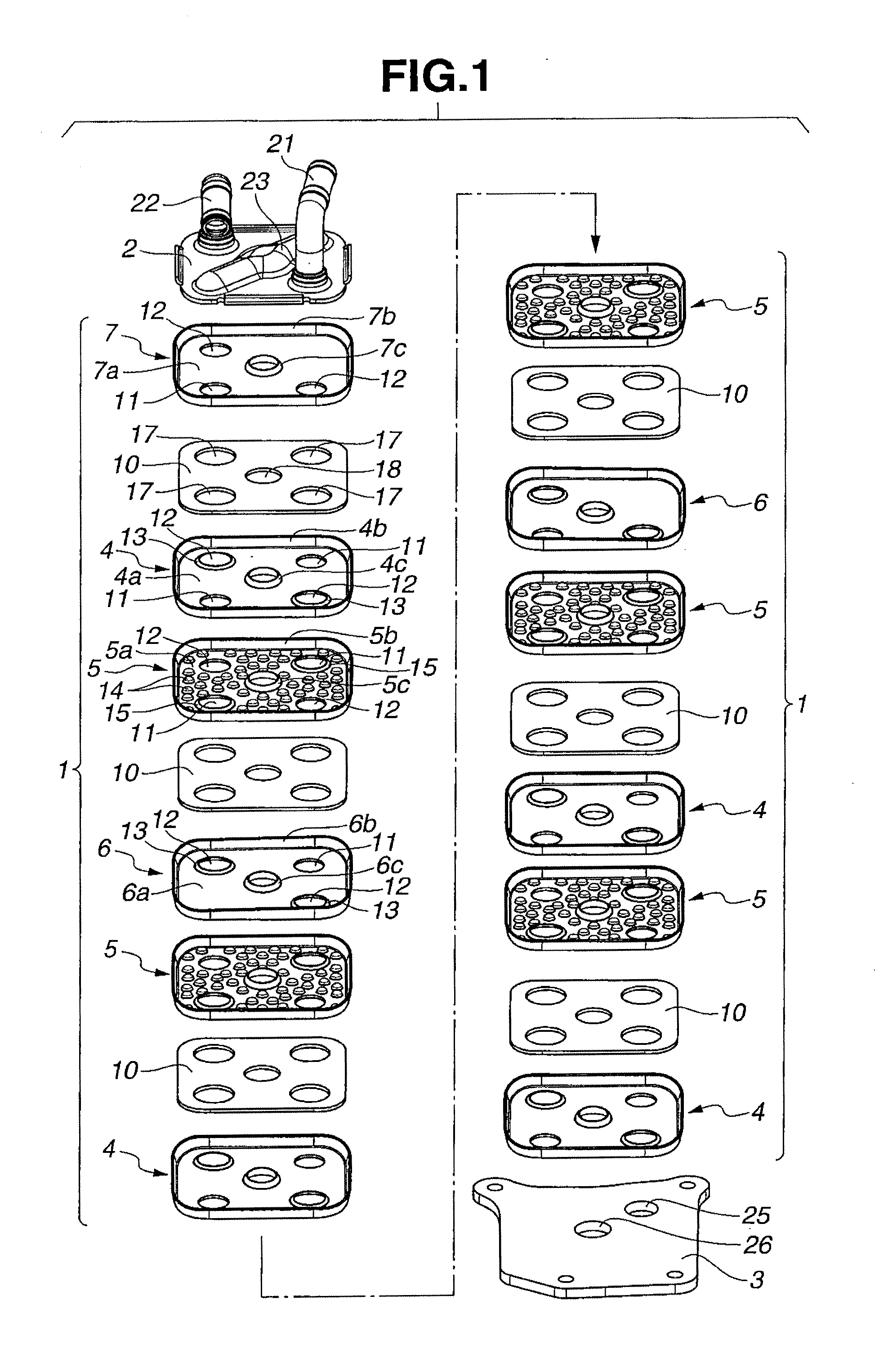
[0035]An oil cooler 100 according to the present invention will be explained hereinafter by referring to FIG. 1 to FIG. 7.

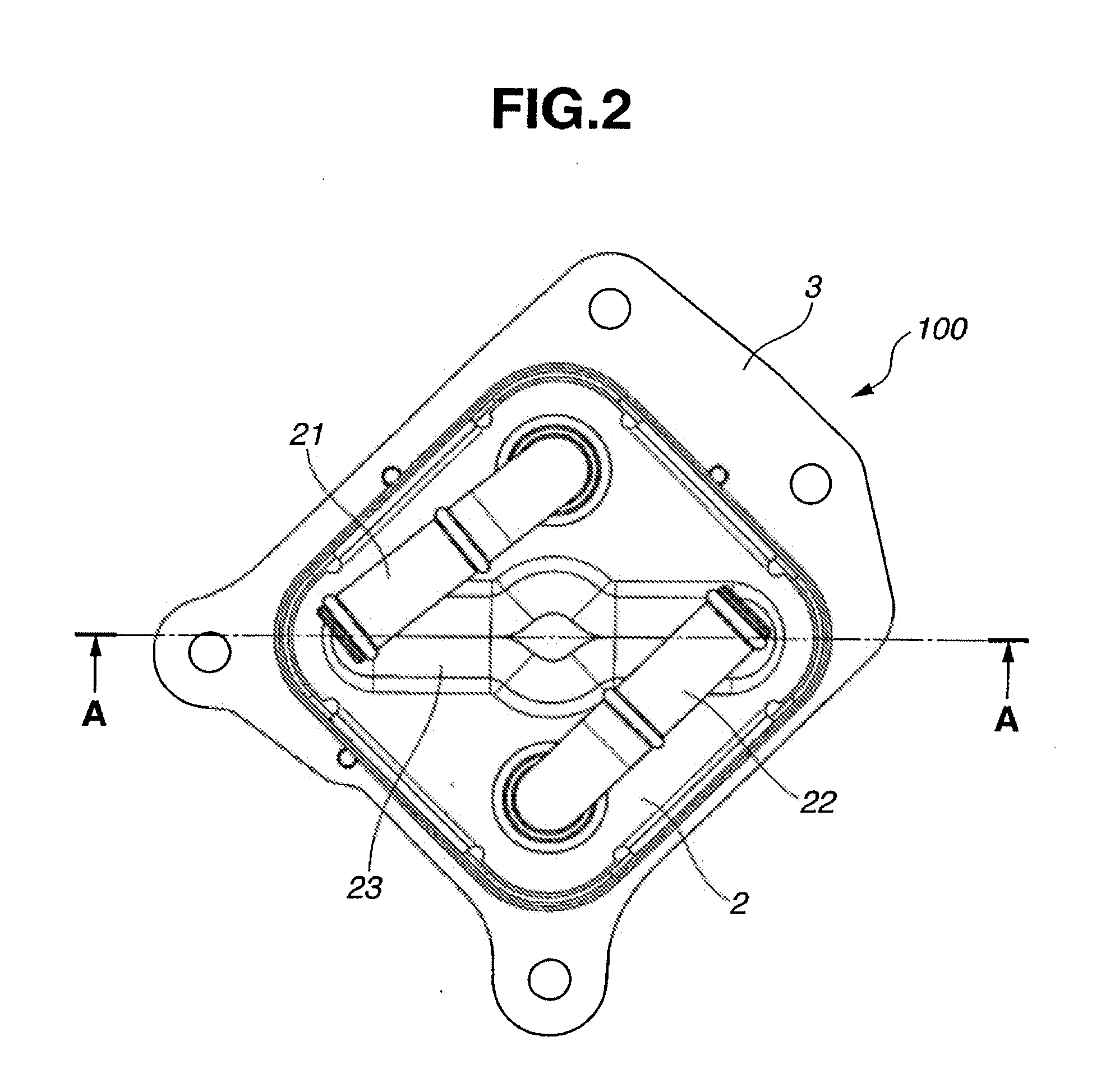
[0036]FIG. 1 is an exploded perspective view of the oil cooler 100. FIG. 2 is a plan view of the oil cooler 100. FIG. 3 is a sectional view of the oil cooler 100, taken along line A-A shown in FIG. 2

[0037]A construction of the oil cooler 100 as a whole is explained. The oil cooler 100 is entirely made of aluminum, for example. As shown in FIG. 1, the oil cooler 100 includes a core module 1 that performs heat exchange between oil and cooling water, a top plate 2 that is mounted to a top surface of the core module 1 and has a relatively large thickness, and a bottom plate 3 mounted to a bottom surface of the core module 1.

[0038]The core module 1 includes four kinds of core plates 4, 5, 6, 7 which basically have substantially the same shape and are stacked on each other in a predetermined order. The core module 1 also includes oil passages 8 and cooling water passag...

second embodiment

[0063]As shown in FIG. 8 and FIG. 9, a height of the circumferential wall 6b of the second core plate 206 in the second embodiment is varied along the circumferential direction of the base wall 6a such that among two pairs of diagonally opposed corner portions 31a, 31b and 31c, 31d, the height at one corner portion 31b of the pair of diagonally opposed corner portions 31a, 31b which is located on the side of the oil communication hole 11 and the height at the pair of diagonally opposed corner portions 31c, 31d respectively located on the side of the cooling water communication holes 12 are largest and equal to each other, and the height at the other corner portion 31a of the pair of diagonally opposed corner portions 31a, 31b is smallest. That is, the circumferential wall 6b of the second core plate 206 is formed such that among the four corner portions 31a, 31b, 31c, 31d, one corner portion 31a (i.e., one of the pair of diagonally opposed corner portions 31a, 31b) which is not loca...

third embodiment

[0067]As shown in FIG. 11 to FIG. 13, a height of the circumferential wall 6b of the second core plate 306 in the third embodiment is varied along the circumferential direction of the base wall 6a as follows. The height at one corner portion 31b of the pair of diagonally opposed corner portions 31a, 31b which is located on the side of the oil communication hole 11 and the height at one corner portion 31d of the pair of diagonally opposed corner portions 31c, 31d which are respectively located on the side of the respective cooling water communication holes 12 are largest and equal to each other. In contrast, the height at the other corner portion 31a of the pair of diagonally opposed corner portions 31a, 31b and the height at the other corner portion 31c of the pair of diagonally opposed corner portions 31c, 31d are smallest and equal to each other. That is, the circumferential wall 6b of the second core plate 306 is formed such that among the two pairs of diagonally opposed corner p...


PUM


Abstract

An oil cooler including a plurality of core plates stacked on each other, the plurality of core plates each including a base wall and a circumferential wall formed along an entire outer periphery of the base wall, and oil passages and cooling water passages alternately arranged in the direction of stacking the core plates. The core plates include at least a first core plate and a second core plate that is different from the first core plate in construction. The circumferential wall of the second core plate has a height being varied along a circumferential direction of the base wall. The circumferential wall of the second core plate is partially higher than the circumferential wall of the first core plate.

Description

BACKGROUND OF THE INVENTION[0001]The present invention relates to a so-called stacked multi-plate oil cooler that is used for cooling a vehicular oil, for instance, a lubricating oil in an internal combustion engine or a working oil in an automatic transmission.[0002]Japanese Patent Application Unexamined Publication No. 11-351778 discloses an oil cooler including a plurality of first plates and a plurality of second plates which are alternately stacked. A cooling water chamber and an oil chamber are alternately formed between the first plate and the second plate in a direction of stacking the plates. The oil chambers adjacent to each other in the direction of stacking the plates are communicated with each other through a pair of oil passages which are formed in the first plate and the second plate, respectively. The cooling water chambers adjacent to each other in the direction of stacking the plates are communicated with each other through a pair of cooling water passages which ar...

Claims


Application Information

Patent Timeline
IPC IPC(8): F28F3/08
CPCF28F2280/06F28F3/044F28D9/0012F28D2021/0089F28D9/005F28D9/0056F28D9/0037
Inventor WAKAMATSU, SHOZOARIYAMA, MASAHIROSATO, JUNKO
Owner MAHLE FILTER SYST JAPAN CORP
Why Eureka
Try Eureka