Jet regulator

a technology of jet regulator and spray nozzle, which is applied in the direction of domestic plumbing, fire rescue, spray nozzle, etc., can solve the problem of less suitable spray jet at the sink

Active Publication Date: 2012-12-27
GROHE
View PDF3 Cites 17 Cited by
  • Summary
  • Abstract
  • Description
  • Claims
  • Application Information

AI Technical Summary

Benefits of technology

[0017]Nevertheless, a large area is to be wetted at a low water pressure, and

Problems solved by technology

In the case of higher water pressure and greater water volume, a spray jet at a

Method used


Image

  • Jet regulator
  • Jet regulator
  • Jet regulator

Examples


Embodiment Construction

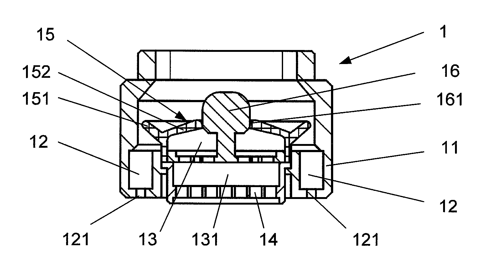
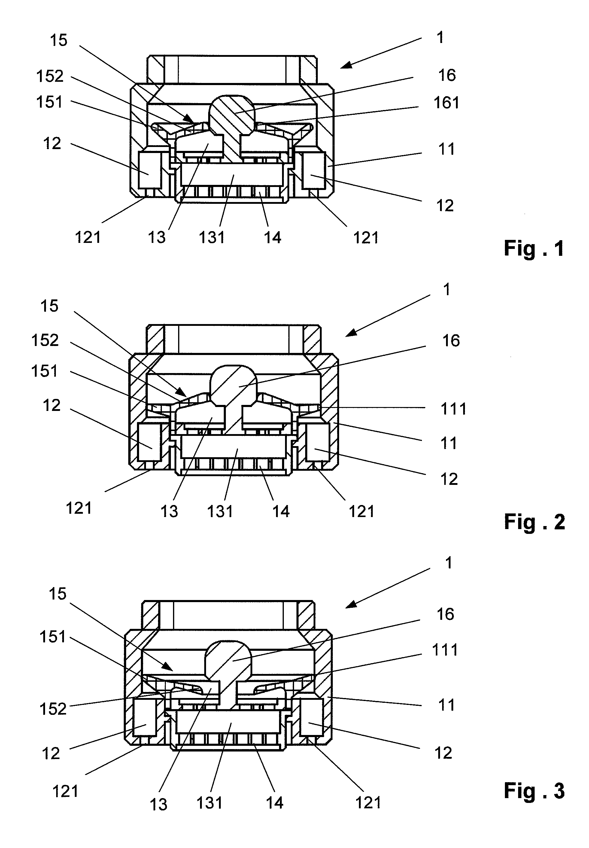
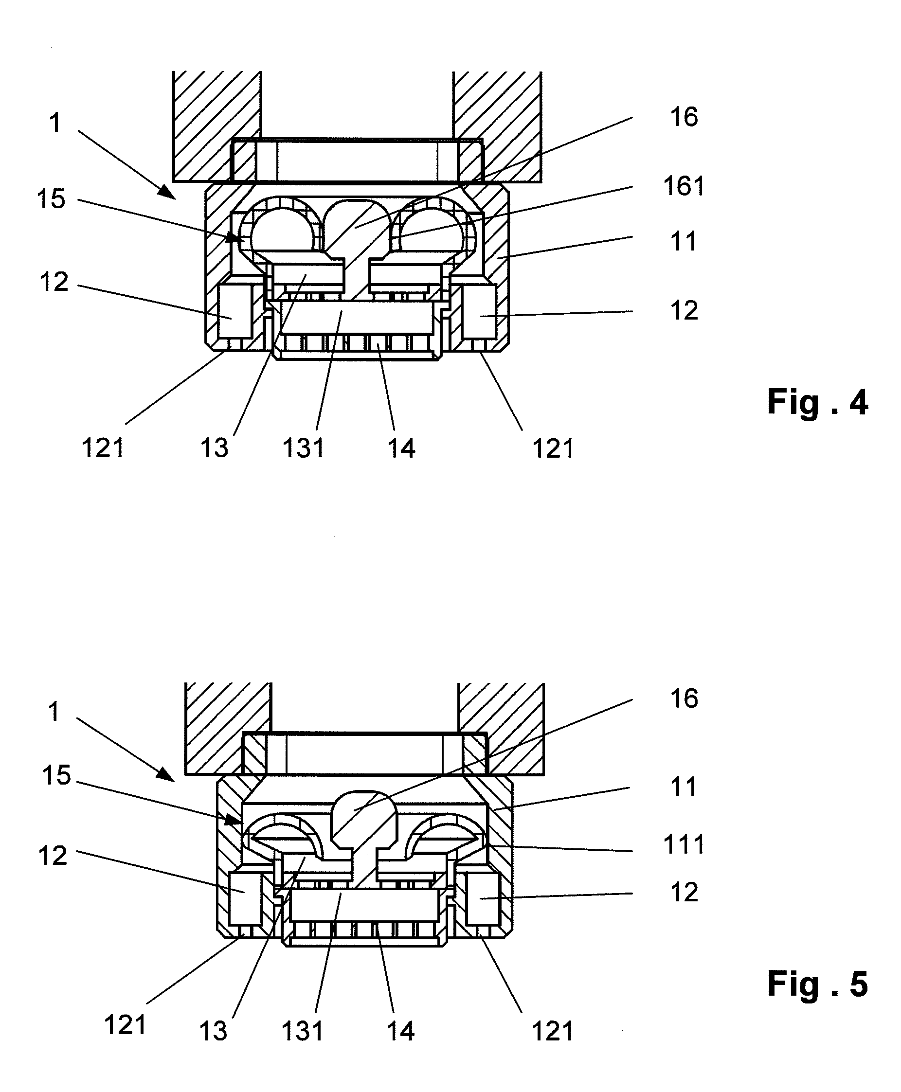
[0031]FIGS. 1 to 3 show a section through a jet regulator 1 of the invention, with a housing 11, whose outer contour is matched to the outlet of a sanitary fitting and whose inner contour defines a part of a flow chamber or a flow channel 12. The present jet regulator 1 has two flow channels 12, 13, which are arranged concentrically to one another. Provided in jet regulator 1 is a valve with a circular ring-shaped elastic valve body 15, whose open and closed positions are achieved by a deformation of valve body 15 and its interaction with different sealing surfaces 111, 161. Elastic valve body 15 has two differently shaped lips 151, 152, which project to both sides of the valve body. Valve body 15 is inserted into jet regulator 1 through the lower opening of housing 11 and simultaneously forms an extension of a flow channel wall. Next, a stamp-shaped insert 16 is inserted into jet regulator 1 also through the lower opening of the housing, said insert against which a lip 152 of the v...


PUM


Abstract

A jet regulator for the outlet of a sanitary fitting or for a shower is provided that has at least two flow chambers or flow ducts, each of which has an inlet opening and one or more water outlet openings, the control of the flow to each flow chamber or flow duct is carried out via a valve having a resilient valve body which is arranged upstream of the flow chambers or flow ducts and optionally closes or opens the inlet openings thereof using the resilient valve body, wherein a deformation of the resilient valve body and thus a change in the valve position is carried out by a change in the applied water pressure or by mechanical actuation via an actuating element.

Description

[0001]This nonprovisional application is a continuation of International Application No. PCT / EP2011 / 000351, which was filed on Jan. 27, 2011, and which claims priority to German Patent Application No. DE 10 2010 006 376.2, which was filed in Germany on Jan. 29, 2010, and which are both herein incorporated by reference.BACKGROUND OF THE INVENTION[0002]1. Field of the Invention[0003]The invention relates to a jet regulator for the outlet of a sanitary fitting or for a shower head.[0004]2. Description of the Background Art[0005]Jet regulators, also called aerators or mixing nozzles, are often located at the water outlet of a sanitary fitting and influence the shape and type of the water jet. Depending on very different country-specific circumstances and different water pressures, the best possible jet is to be assured. Typically, a soft but not spraying jet is to be produced and water and energy costs to be saved. There are jet regulators with an aerated jet, laminar jet, and spray jet...

Claims


Application Information

Patent Timeline
IPC IPC(8): E03C1/08
CPCB05B1/16B05B1/18E03C1/084B05B1/34B05B1/3006B05B1/3402
Inventor GRANSOW, ECKHARDBUSCHEY, WERNER
Owner GROHE
Why Eureka
Try Eureka