Power tool storage case

a technology for power tools and storage cases, applied in the field of power tool storage cases, can solve the problems of battery packs colliding with each other and being damaged, and achieve the effects of enhancing the stability of the battery pack, facilitating installation, and ensuring the rigidity of the plate members

Inactive Publication Date: 2012-12-27
MAKITA CORP
View PDF2 Cites 14 Cited by
  • Summary
  • Abstract
  • Description
  • Claims
  • Application Information

AI Technical Summary

Benefits of technology

[0005]In light of the above, the present invention provides a power tool storage case providing excellent usability that can hold a backup battery pack in a stable manner without any wobble, in what is originally a charger storage portion.
[0012]According to the first aspect of the invention, the original charger storage portion has excellent ease of use and can hold a backup battery pack in a stable manner without the battery pack moving around.
[0013]According to the second aspect of the invention, in addition to the benefits of the first aspect, it is possible to hold a sufficient number of the backup battery packs, thus further improving usability.
[0015]According to the fourth aspect of the invention, in addition to the benefits of the first aspect, it is possible to select whether to hold one of the charger and the battery pack by a simple operation of installing and removing the retaining members.
[0016]According to the fifth aspect of the invention, in addition to the benefits of the fourth aspect, it is possible to secure the rigidity of the plate members and thus to enhance the stability of the battery pack when the battery pack is held in the charger storage portion.
[0017]According to the sixth aspect of the invention, in addition to the benefits of the first aspect, it is possible to hold the battery pack more reliably.

Problems solved by technology

However, at an actual work site, it is sometimes necessary to carry an extra backup battery pack to work in place of the charger, rather than carrying the power tool main body, the backup battery pack and the charger together as a set.
In this case, as the battery packs are stored in a space that is larger than the battery pack, it is easy for the battery packs to move around while being carried and there is a risk of battery packs colliding with each other and being damaged.

Method used


Image

  • Power tool storage case
  • Power tool storage case
  • Power tool storage case

Examples


first embodiment

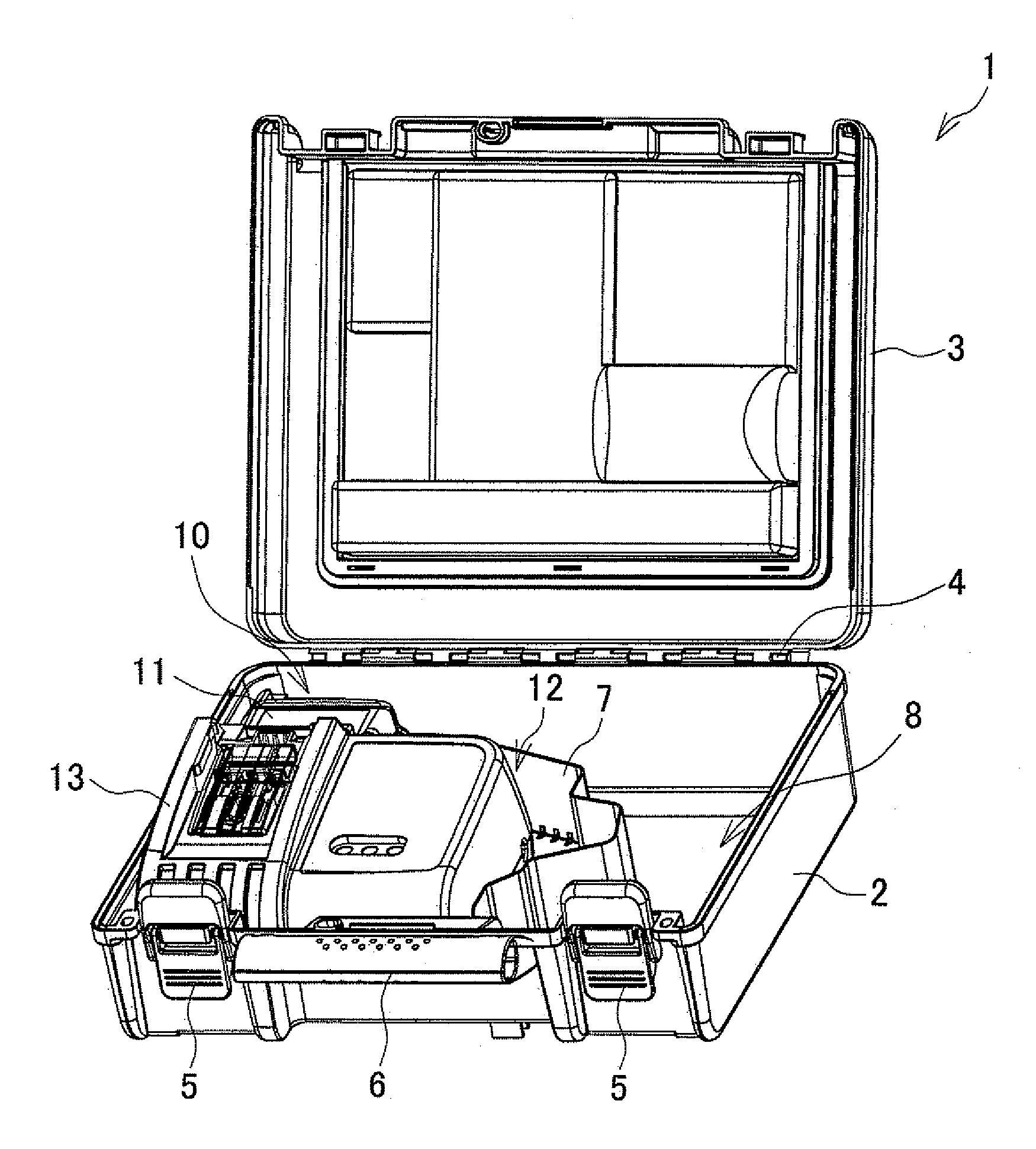
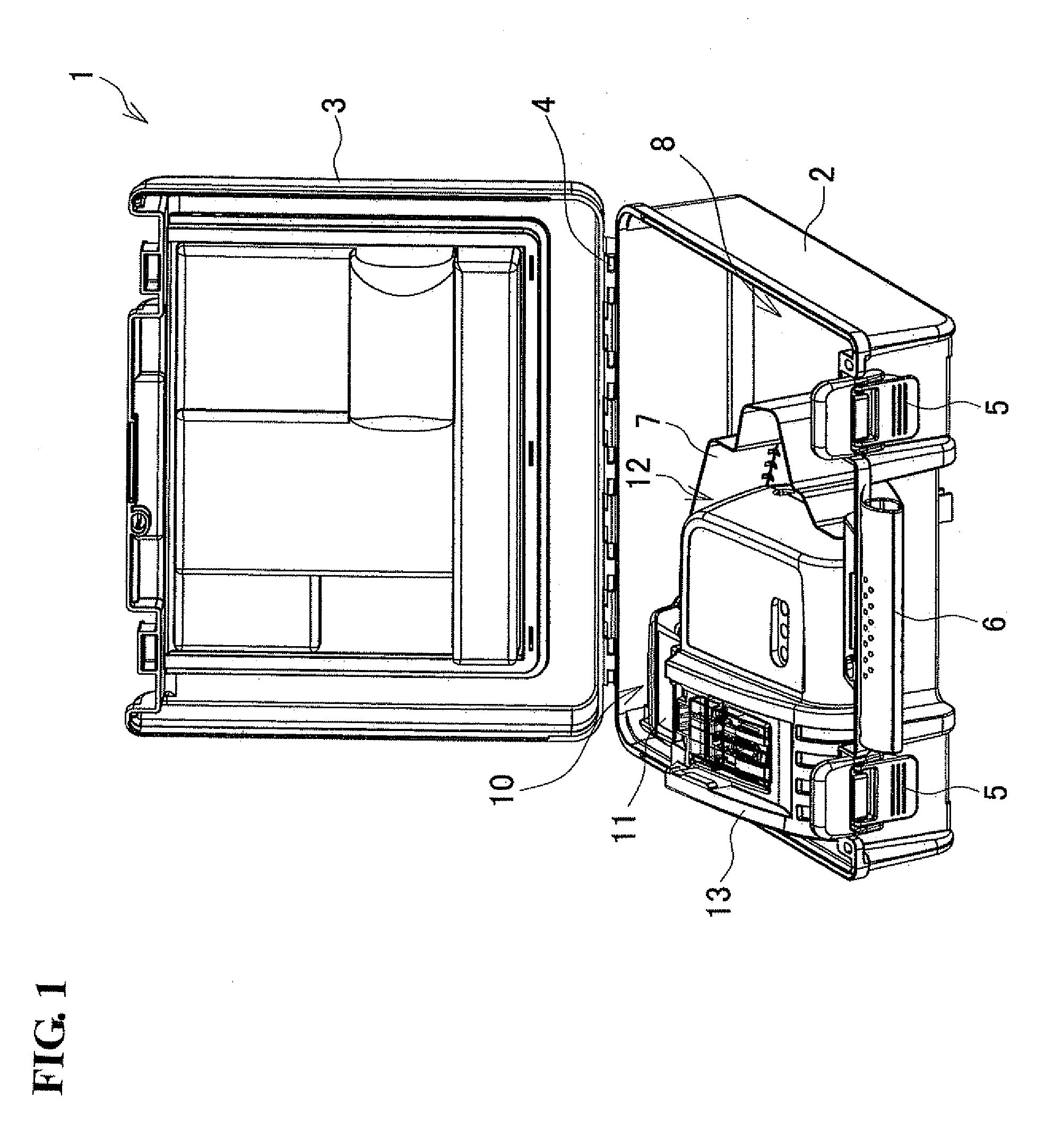
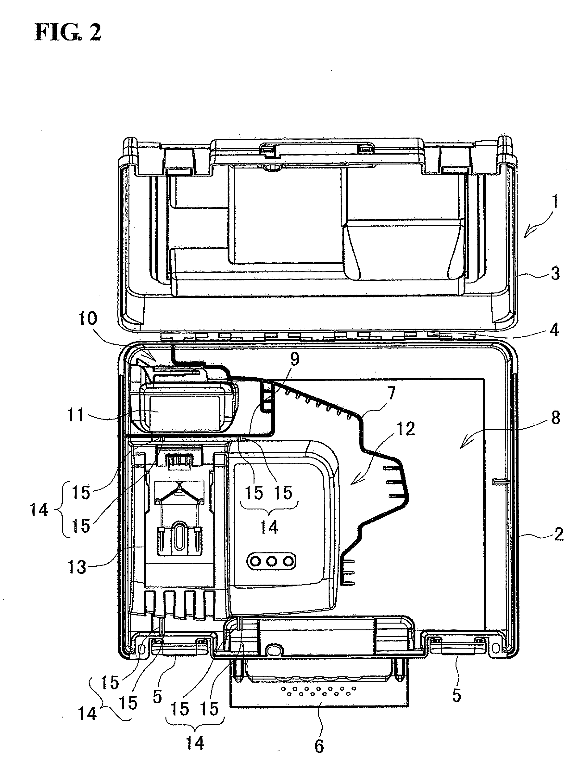
[0032]FIG. 1 and FIG. 2 show one example of a power tool storage case (hereinafter simply referred to as a “storage case”). A storage case 1 is made of synthetic resin and includes a deep, square box shaped main case 2 and a shallow lid 3 that has the same square box shape as the main case 2. Each of the main case 2 and the lid 3 are injection molded. The main case 2 and the lid 3 are hinge jointed such that an opening on an upper side of the main case 2 and an opening on a lower side of the lid 3 are aligned with each other in a closed state and opening edges on a rear surface (when the lower left side in FIG. 1 (the lower side in FIG. 2) is a frontward direction) can be rotated with respect to each other by a shaft 4.

[0033]Further, opening edges of the main case 2 and the lid 3 on a front side can be mutually locked and unlocked using a pair of left and right latches 5, and a handle 6 is provided on a front surface of the main case 2 between both the latches 5.

[0034]In addition, a...

second embodiment

[0047]Next, another embodiment of the present invention will be explained. It should be noted that, where structural portions are the same as those of the first embodiment, the same reference numerals are assigned and an explanation is omitted.

[0048]In a storage case 1A shown in FIG. 8 and FIG. 9, the main case 2 and the lid 3 are formed by so-called blow molding, and a tool storage portion 30 is formed in the bottom surface of the main case 2 on the right side. The tool storage portion 30 is recessed to conform to an outer shape of a rechargeable power tool. Further, in the center of the main case 2 and to the left side of the tool storage portion 30, two battery storage portions 31 are formed and are recessed to conform to an outer shape of the battery pack 11. In addition, on the left side of the main case 2, a charger storage portion 32 is formed and is recessed to conform to an outer shape of the charger 13.

[0049]Meanwhile, upper recesses 33 are also formed in the underneath su...


PUM


Abstract

A power tool storage case includes a main case that has a tool storage portion, a battery storage portion and a charger storage portion, and a lid that can open and close the main case. The charger storage portion is a dual-purpose storage portion that can hold one of a charger and a battery pack in accordance with selection of one of the charger and the battery pack.

Description

BACKGROUND OF THE INVENTION[0001]This application claims the benefit of Japanese Patent Application Number 2011-142014 filed on Jun. 27, 2011, the entirety of which is incorporated by reference.TECHNICAL FIELD[0002]The present invention relates to a power tool storage case that is used to store a rechargeable power tool, such as an impact driver or the like, and accessories of the rechargeable power tool.BACKGROUND ART[0003]Power tool storage cases are known for rechargeable power tools, such as an impact driver etc., in which accessories, such as replacement bits (tool tips), a battery pack that is used as a power source, a charger for the battery pack and so on, are stored together with the power tool main body. The power tool and its accessories can thus be carried and stored at the same time. Such a power tool storage case is disclosed in Japanese Patent Application Publication No. JP 2006-205323 A, in which a plurality of ribs are provided in a standing manner inside a square b...

Claims


Application Information

Patent Timeline
Patent Type & Authority Applications(United States)
IPC IPC(8): H02J7/00
CPCB25H3/022B25H3/006
Inventor HORIYAMA, TORUKANOU, ATSUSHIWAKATSUKI, SHUSAKUBITO, SHINYA
Owner MAKITA CORP
Why Eureka
Try Eureka