Remote Node and Network Architecture and Data Transmission Method for a Fiber-Optic Network, Especially for Low Bit-Rate Data Transmission

a fiber-optic network and data transmission technology, applied in the direction of transmission, star-type electromagnetic networks, electromagnetic transmission, etc., to achieve the effect of low bandwidth

Active Publication Date: 2012-12-27
ADVA OPTICAL NETWORKING SE
View PDF9 Cites 14 Cited by
  • Summary
  • Abstract
  • Description
  • Claims
  • Application Information

AI Technical Summary

Benefits of technology

[0007]The invention is based on the finding that optically passing through the digital optical signal to be transmitted through each of the remote nodes on its way between a selected one of the remote nodes and the central node or vice versa, which results in realizing a linear fiber-optic bus structure, and (at any rate or if necessary due to signal deterioration) additionally creating an echo signal in one or more (or all) remote nodes

Problems solved by technology

Thus, if the digital optical transmit signal is, on its way to the receiving remote or central node, deteriorated such that the signal quality cannot guarantee receiving t

Method used


Image

  • Remote Node and Network Architecture and Data Transmission Method for a Fiber-Optic Network, Especially for Low Bit-Rate Data Transmission
  • Remote Node and Network Architecture and Data Transmission Method for a Fiber-Optic Network, Especially for Low Bit-Rate Data Transmission
  • Remote Node and Network Architecture and Data Transmission Method for a Fiber-Optic Network, Especially for Low Bit-Rate Data Transmission

Examples


Embodiment Construction

)

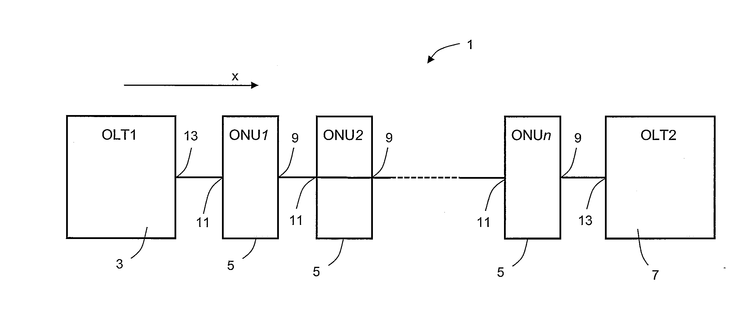
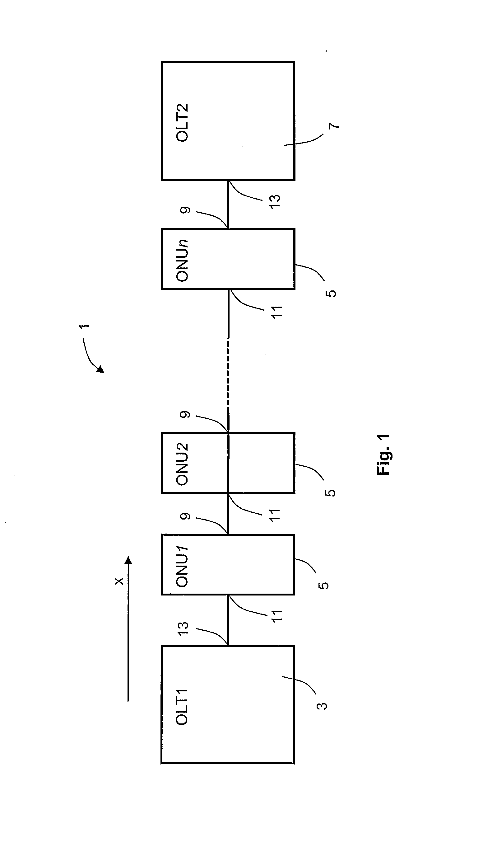
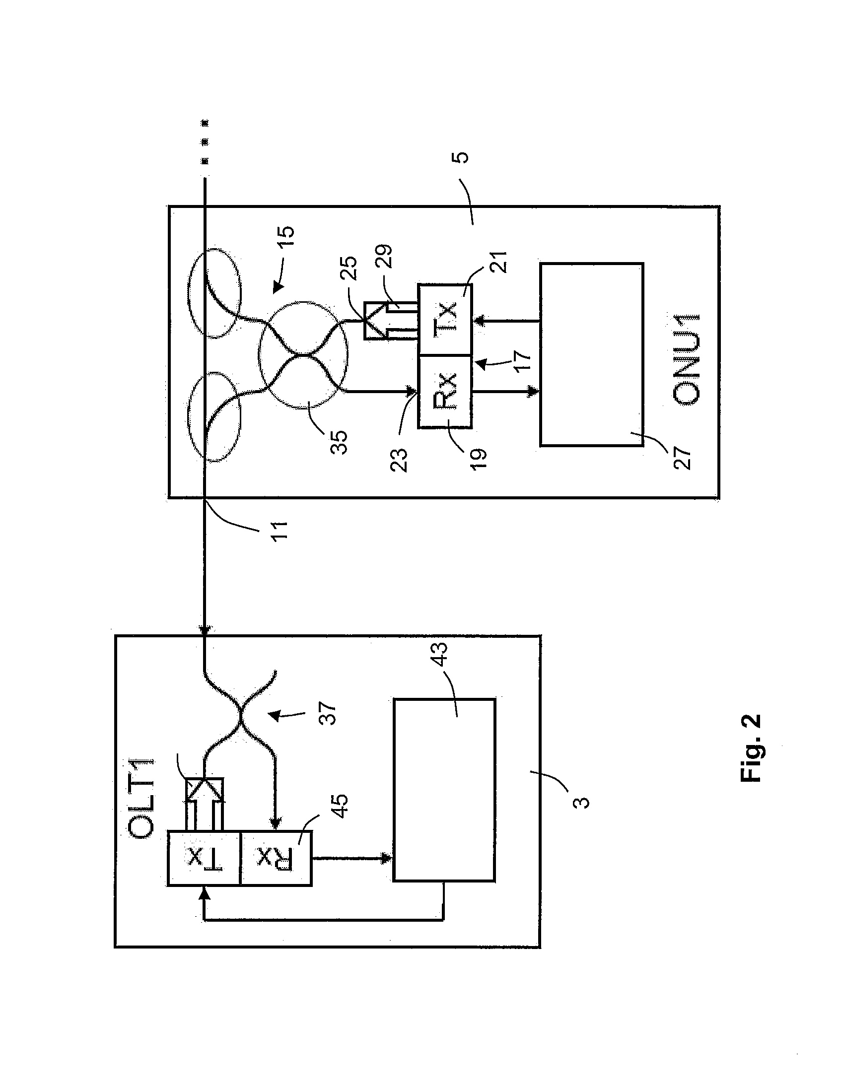
[0046]FIG. 1 shows a schematic block diagram of a fiber-optic network architecture 1 comprising a western central node 3, also designated as “optical line terminal” OLT1, a plurality of N remote nodes 5, also designated as “optical node units” ONUi with i=1, . . . N, and a second or eastern central node 7, also designated as “optical line terminal” OLT2. The remote nodes 5 are connected in the form of a chain wherein each remote node 5 includes an eastern and western optical connection port 9, 11. The single connection port 13 of the western central node 3 is connected to the western connection port 11 of the first of the remote nodes 5, and the single connection port 13 of the eastern central node 7 is connected to the eastern connection port 9 of the Nth remote node 5. Further, the eastern connection port 9 of a first of two neighboring remote nodes 5 is connected to the western connection port 11 of the second one of the two neighboring remote nodes 5. The respective ports are c...


PUM


Abstract

The invention relates to a remote node architecture for a fiber-optic network, especially for low bit-rate data transmission, the fiber-optic network comprising a central node and a plurality of remote nodes serially connected to each other or to the central node, respectively, the central node and the remote node being capable of communicating by means of digital optical signals created by the central node or a respective remote node, each digital optical signal comprising a data frame.

Description

BACKGROUND OF THE INVENTION[0001]1. Field of the Invention[0002]The invention relates to a remote node architecture for a fiber-optic network, especially for low bit-rate data transmission, and to a fiber-optic network architecture comprising such remote node architectures as well as to a data transmission method suitable therefore.[0003]2. Description of Related Art[0004]Recently, especially in the context of the so-called “smart metering” application, public or private utility companies have started to deploy their own communication networks. These networks (referred to as sensor networks in the following) may, for example, connect commercial end users to the different levels of voltage transformer stations. These may be low voltage, medium voltage or high voltage transformers or even the respective energy dispatch center. To a wide extent, optical fiber infrastructure will be used for these communication networks. The whole network setup and hierarchy is quite similar to a teleco...

Claims


Application Information

Patent Timeline
IPC IPC(8): H04B10/20
CPCH04B10/278H04B10/272H04B10/275
Inventor GROBE, KLAUSHINDERTHUR, HENNING
Owner ADVA OPTICAL NETWORKING SE
Why Eureka
Try Eureka