Optical Spectrum Recovery

a spectrum recovery and optical technology, applied in the field of optical spectrum recovery, can solve the problems of inefficient use of available spectrum, stranded spectrum, and no adequate contiguous portion

Active Publication Date: 2012-12-27
TECHSYS INSIGHTS
View PDF1 Cites 41 Cited by
  • Summary
  • Abstract
  • Description
  • Claims
  • Application Information

AI Technical Summary

Benefits of technology

[0018]As may be apparent from the embodiments disclosed herein, the invention offers several advantages over the prior art. The invention allows for the rearrangement of spectrum and hence the recovery of unallocated portions into larger contiguous portions in a manner which may not require the traffic carried by the channels which are rearranged to be interrupted during the rearrangement process. Further, the invention may be realized through the inve

Problems solved by technology

Channel schemes which employ fixed spectral width allocations may lead to inefficient use of the available spectrum.
However, this variable spectral width allocation scheme, or any allocation scheme that uses variable sized allocations in a contiguous spectral range per channel can lead to the case where unallocated spectrum may become interspersed with allocated spectrum leading to “stranded” spectrum.
That is, aggregation(s) of unallocated spectrum may be sufficient to handle additional allocation demands, but fragmentation may mean that there is no adequate contiguous portion.
This reduces the spectrum utilization.
However, as a client moves channels to alt

Method used


Image

  • Optical Spectrum Recovery
  • Optical Spectrum Recovery
  • Optical Spectrum Recovery

Examples


Embodiment Construction

[0030]The present invention will now be described more fully, using a subset of its embodiments. Additional embodiments will be apparent to those skilled in the art and are covered by the claims of the invention.

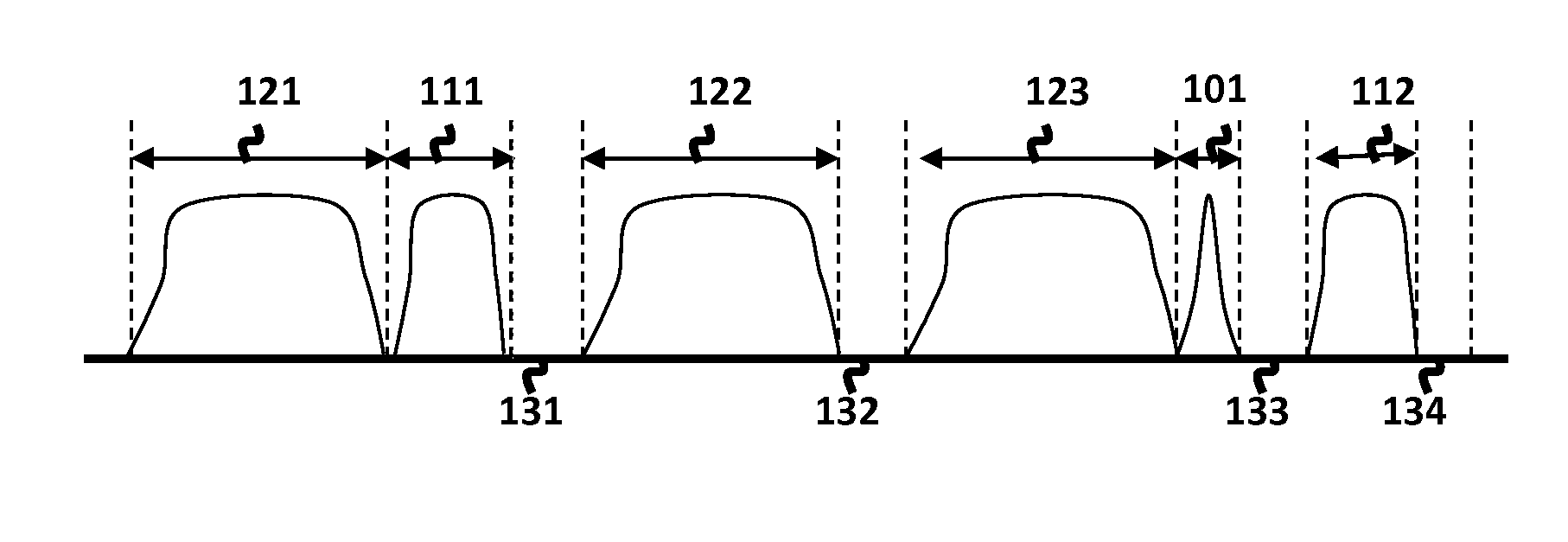
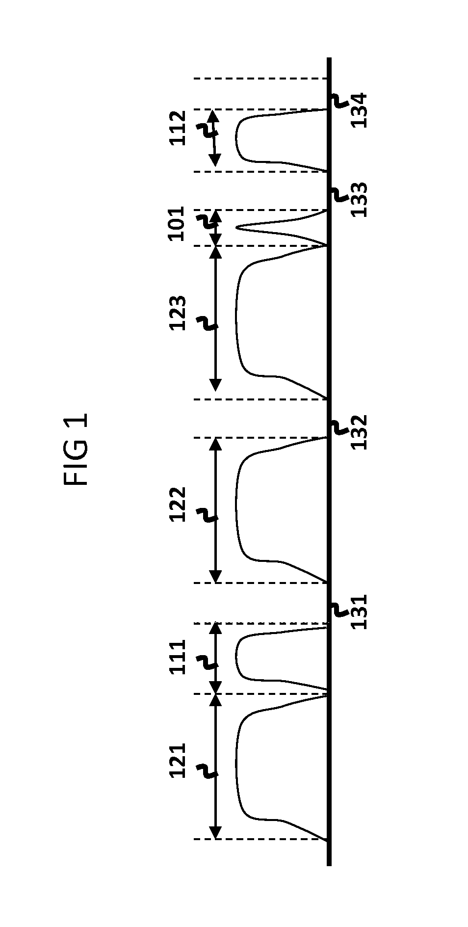
[0031]Optical communications systems transmit optical signals from an optical origination point to one or more optical termination points. These optical signals may be modulated in some fashion in order to carry information. An optical signal may be characterized by its center frequency, state(s) of polarization and its spectral width. The minimum portion of the optical spectrum required by a given system to be allocated for the conveyance of a given optical signal from an origin to one or more termination(s) is referred to as an optical channel, which is often, in context, simply referred to as a channel. More specifically, allocation refers to one or more portions of optical spectrum reserved for the channel and within which the system must constrain the optical signal. Th...


PUM


Abstract

The invention is directed to systems and methods for re-arranging optical spectrum utilization so that unallocated portions of the spectrum may be made contiguous. Rearrangement of optical spectrum is accomplished by moving a channel from its initial spectral location to a targeted spectral location by reserving additional spectrum for that channel that at least includes the targeted spectral location, shifting the channel to the targeted location and then collapsing the reserved spectrum around the targeted location to cover the minimal required spectrum for the channel allocation of the channel. In some cases, a secondary channel can be used as an alternate source to carry user traffic while the first channel is shifted to the targeted location.

Description

CROSS REFERENCE TO RELATED APPLICATIONS[0001]Not applicable.STATEMENT REGARDING FEDERALLY SPONSORED RESEARCH OR DEVELOPMENT[0002]Not applicable.BACKGROUND OF THE INVENTION[0003]Optical communication systems often employ Wavelength Division Multiplexing (WDM) with channel plans involving fixed sized allocations of spectrum per channel, each at an assigned center wavelength. Each channel is thus reserved or allocated a specific portion of the optical spectrum such that multiple channels may be transmitted simultaneously through a fiber optical strand or other medium, including free space, thus providing an information carrying capacity.[0004]Channel schemes which employ fixed spectral width allocations may lead to inefficient use of the available spectrum. High data rate channels may, for example, require a larger amount of spectrum while lower rate channels may be able to employ smaller amounts of spectrum. In this mixed rate environment, employing adaptable or variable spectral widt...

Claims


Application Information

Patent Timeline
IPC IPC(8): H04J14/02
CPCH04J14/026H04J14/0279H04J14/0204H04J14/0275H04J14/021H04J14/0212H04J14/0257H04J14/0205
Inventor SULLIVAN, EDWARD T.KAUFFELDT, HAL
Owner TECHSYS INSIGHTS
Why Eureka
Try Eureka