Sun tracking solar power collection system

Inactive Publication Date: 2013-01-03
ADVANCED TECH & RES CORP
View PDF5 Cites 29 Cited by
  • Summary
  • Abstract
  • Description
  • Claims
  • Application Information

AI Technical Summary

Benefits of technology

[0029]A further object of this invention is to provide a m

Problems solved by technology

This would not be an effective approach if the purpose was to generate excess electrical power to be fed back into the electrical grid.
This approach does not lend itself for retrofitting onto existing utility poles and it would also be impossible to use on a wind turbine pole where the top of the pole is occupied by the turbine itself.
This design limits the potential installation sites.
These top mounted configurations cannot be easily mounted to the midsection of the pole where ther

Method used


Image

  • Sun tracking solar power collection system
  • Sun tracking solar power collection system
  • Sun tracking solar power collection system

Examples


Example

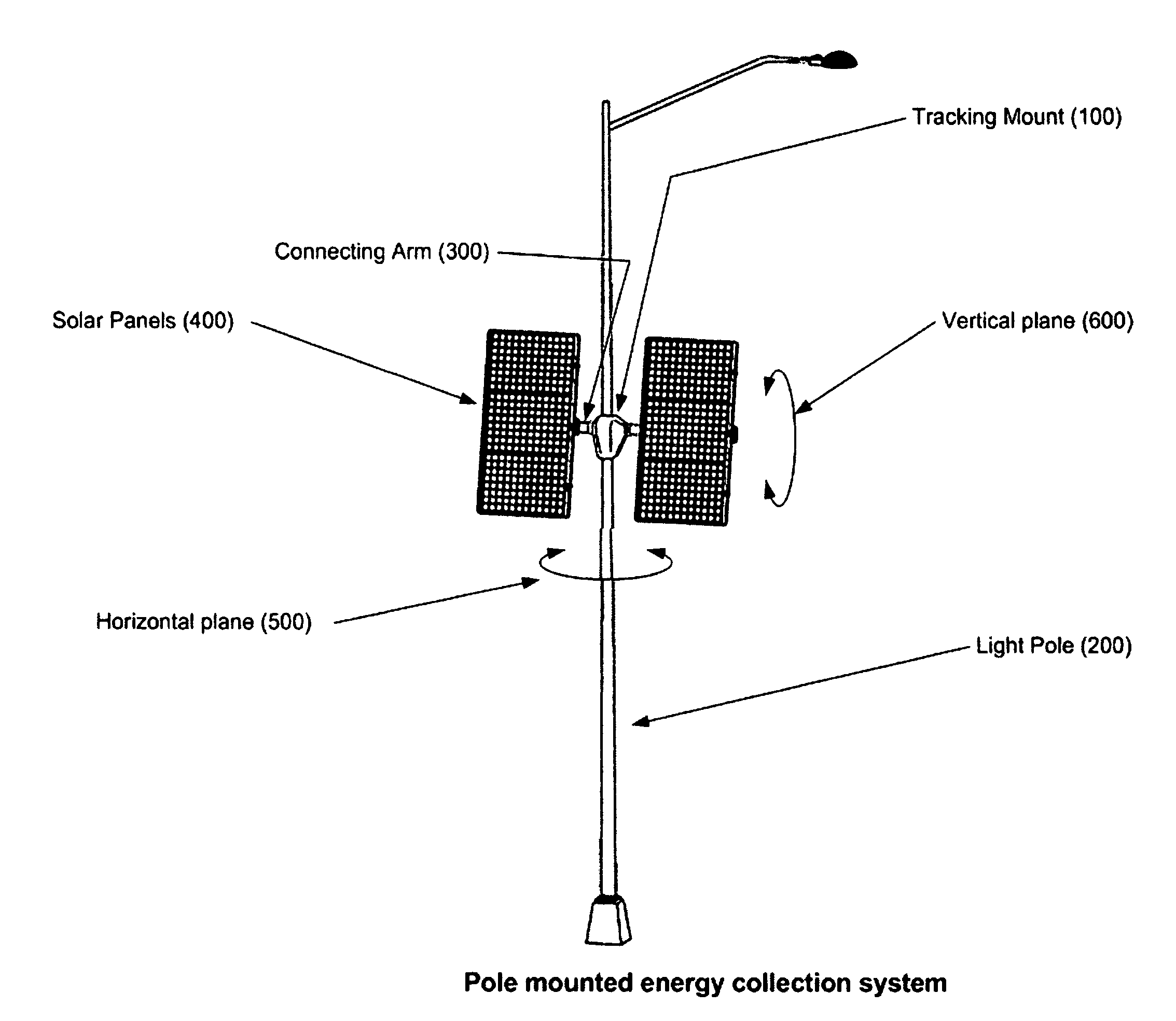
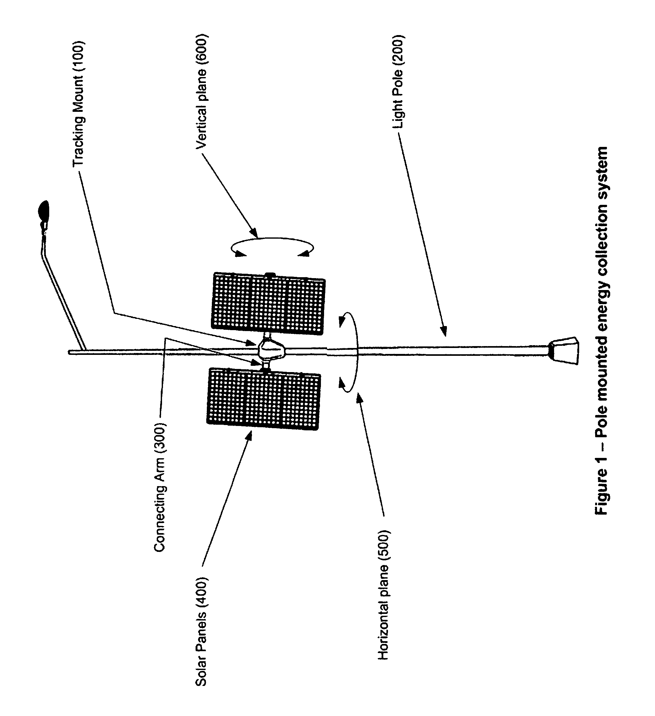
[0042]The following sections describe the invention where the application is for mounting a solar panel tracking system onto light poles and wind turbine support poles. It should be obvious that this invention can also be utilized as a simple and robust method for building a sun tracking solar collection system on practically any pole structure including a single purpose pole dedicated to the mounting of the solar panel. Similarly this invention could also be applied to a variety of different pointing applications for antennas or other optical systems.

[0043]FIG. (1) Pole mounted sun tracking solar panel mount—This illustration shows an the pole mounted sun tracking solar panel mount installed on a utility light pole. Using an existing light pole provides a cost effective approach for mounting the solar power collection system. The abundance of existing lighting fixtures provides immediately available installation sites. Existing utility light polls provide an easy access to the loca...


PUM


Abstract

This invention presents a unique design for a sun tracking, solar panel mounting system that is intended to be mounted onto utility light poles, wind turbine poles, and other pole type structures. Rings are clamped around the pole and form a structural interface to support the tracking mount assembly and allow it to rotate around the centerline of the pole. An actuator powers the tracking structure rotate right or left around the centerline of the pole. A secondary structure in the mount assembly supports solar panels on either side of the vertical mounting poll and an optional second actuator tilts the elevation solar panels up and down. A control system reads the position of each actuator and periodically adjusts them to track the motion of the sun and optimize the solar energy collection efficiency.

Description

BACKGROUND OF THE INVENTION[0001]1. Field of the Invention[0002]This invention relates to solar energy electrical power collection systems and specifically to the design of a solar panel mounting system that is mounted on pole structures and tracks the movement of the sun with a single or dual axis motion and programmable control.[0003]Utility poles for lighting, power, communications, and wind turbines are prevalent in today's landscape. They are existing industrial structures that can be utilized to support solar panels and they also provide convenient access to the local power grid. These are attractive features for solar power collection systems as part of a distributed generation system. Using existing poles for a mounting structure greatly reduces the cost to install the solar panels and no additional real estate is required. Utilizing existing poles also provides an easy access to the electrical grid so that power produced by the solar panels does not need to be stored but ca...

Claims


Application Information

Patent Timeline
IPC IPC(8): F24J2/38
CPCY02E10/50Y02E10/47H02S20/00G01S3/7861F24J2/542G09F23/00H02S20/32
Inventor LUNDAHL, ROBERT D.CUTLIP, ROBERT
Owner ADVANCED TECH & RES CORP
Why Eureka
Try Eureka