Wind-load-resisting type spot type condenser

A concentrator and point-type technology, applied in the field of solar energy applications, can solve the problems of weakening the blowing force of the concentrator, focusing failure, tracking failure, etc., and achieve the effect of improving overall energy efficiency, improving tracking accuracy, and facilitating large-scale

Inactive Publication Date: 2020-02-07
PULIN TAIYANG ZHENGZHOU ENERGY POWER
View PDF0 Cites 2 Cited by
  • Summary
  • Abstract
  • Description
  • Claims
  • Application Information

AI Technical Summary

Problems solved by technology

[0002] At present, limited by manual or mechanical tracking methods, the thermal efficiency of small solar cookers is poor. With the application of automatic solar tracking devices, the thermal efficiency of solar cookers has been greatly improved, but affected by the structure, solar concentrators (solar cookers) The focus of the solar cooker is generally obliquely above the solar concentrator (solar cooker) (that is, between the solar cooker and the sun), which brings inconvenience to the installation and use of solar cooker heat collectors such as pots and water tanks. The focal point of the solar concentrator (or solar cooker) is obliquely below the solar concentrator, but affected by its non-wind guiding structure, no matter the wind comes from the concentrator to the light or the backlight direction, because the wind has no shunt channel, the concentrator The wind load of the optical device is large, which will cause the tracking drift of the device. In severe cases, the tracking will fail, resulting in focusing failure, making the photothermal conversion efficiency of the concentrating solar energy utilization device low or invalid. In addition, the heat collector (such as a solar cooker) Below the concentrator, the spatial dimension of the concentrator and the heat collector (such as a solar cooker) is long in the direction of the sun's incident light, so that the concentrator takes up a large space for turning on the automatic sun tracking device. Therefore, If a windy channel is invented, the focusing position (that is, the installation position of the heat collector) is below or inside the concentrator, and the transmission and reflection are directly concentrated to the same place (that is, the focal point), the concentrator can be It has the advantage that the focal point of the solar concentrator (such as a solar cooker) is below the concentrator (such as a solar cooker), and it also overcomes the disadvantage of changing the light path twice or more before concentrating, and can weaken the wind blowing on the concentrator. In this way, it can improve the anti-wind load capacity of the concentrator and reduce the tracking deviation, thereby improving the overall energy efficiency of the tracking solar concentrator (solar cooker) photothermal conversion device. The installation position of the solar collector) in the concentrator reduces the space occupied by the concentrator and the heat collector (such as a solar cooker) in the case of automatic tracking, and reduces the space occupation of the entire solar photothermal conversion device, which is beneficial Large-scale solar photothermal conversion device

Method used


Image

  • Wind-load-resisting type spot type condenser
  • Wind-load-resisting type spot type condenser
  • Wind-load-resisting type spot type condenser

Examples


Embodiment 1

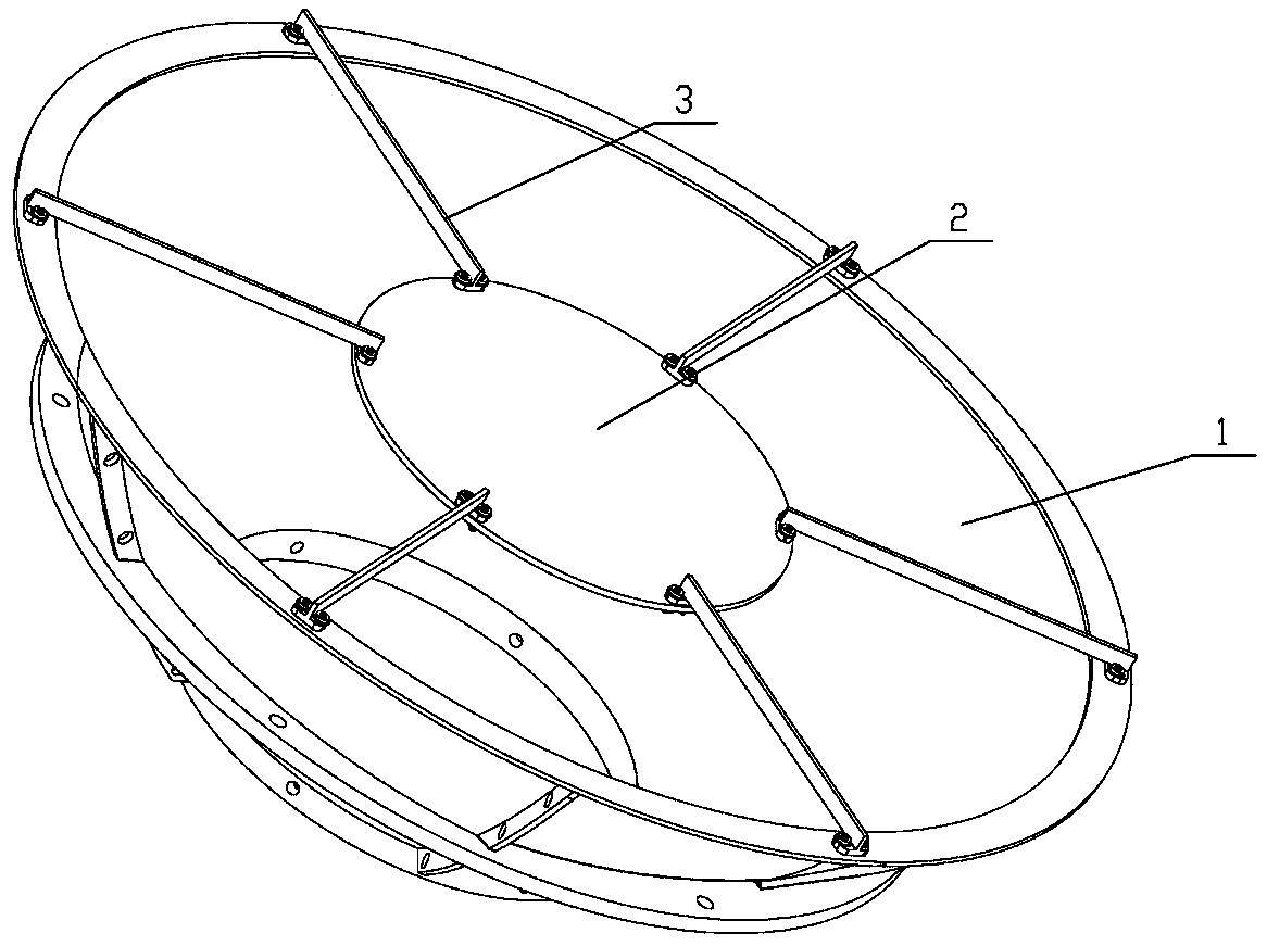
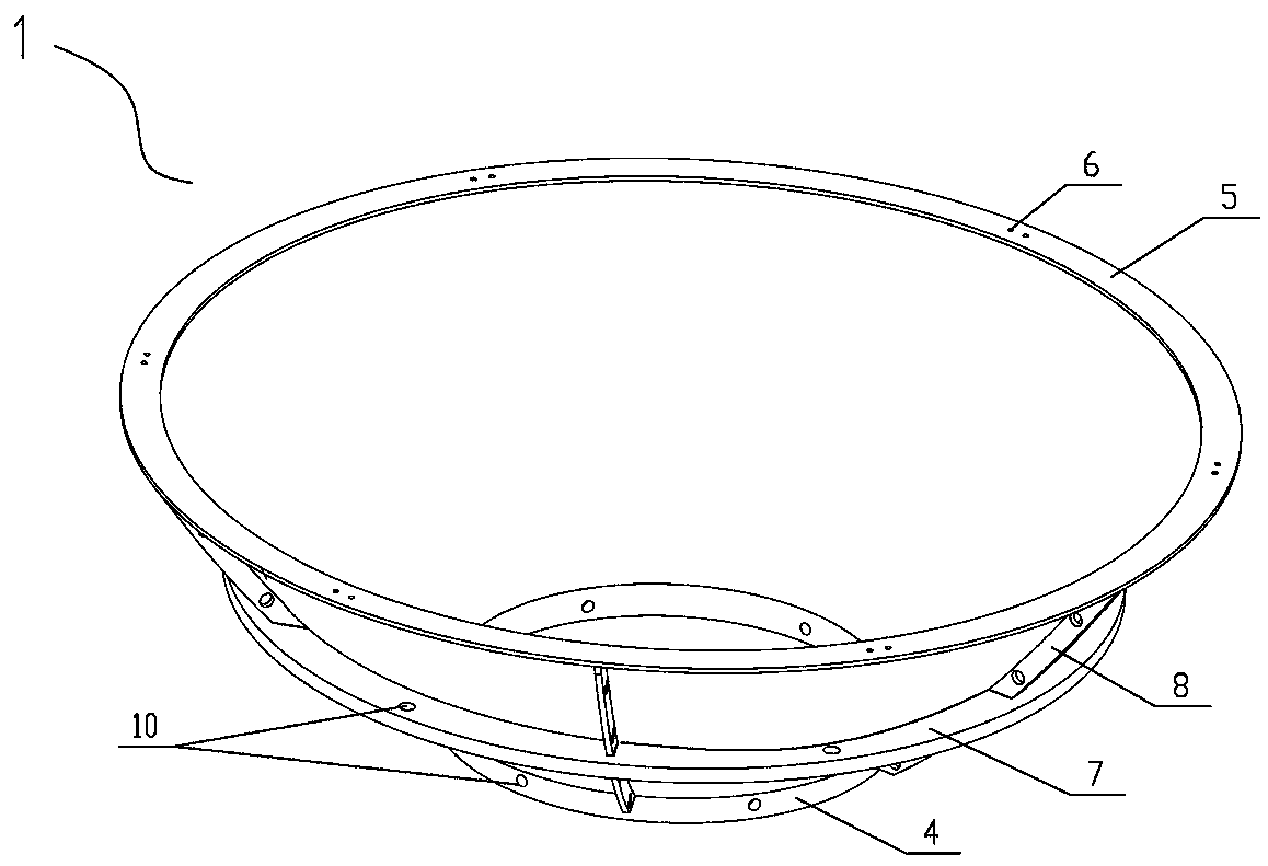
[0021] Embodiment 1: When the present invention is in use, the diameter of the lens of the transmission concentrating component 2 is 0.8 meters, the focal length is 0.75 meters, and the diameter of the open end opening 5 of the paraboloid of the reflective concentrating component 1 is 2.8 meters, and the present invention is installed. On the device that can automatically track both north-south and east-west directions, under the wind condition of grade 4-5 southeast wind, compared with other concentrators with no airflow channel on the overall light receiving surface, the focal spot of the sun light is focused. The deviations in the north-south and east-west directions are greatly reduced throughout the day, that is, the focus fluctuation of the wind blowing from the light facing side to the present invention is small. When concentrating light in the present invention, the open end opening 5 of the reflective concentrating member 1 faces the sun, the central axis of symmetry o...

Embodiment 2

[0022] Embodiment 2: The present invention is installed on the automatic tracking device, the diameter of the open end opening 5 of the paraboloid of the reflective light-converging component 1 used is 2.8 meters, the diameter of the top opening 4 is 0.8 meters, and the lens of the transmission light-converging component 2 is 0.8 meters. The outer diameter is 0.8 meters, and the focal length is 0.75 meters. In early winter, when the northwest wind is 4~5, the condenser can be located at the focal point (spot) of the condenser between 11:30 a.m. and 12:30 p.m. 20 kg of water with an initial temperature of 16 °C was heated to 98 °C in 30 minutes.

[0023] The invention overcomes the shortcoming that point-type focusing can only be achieved by multiple reflection and transmission, adopts the optical path principle of coincidence of transmission and reflection focal points, and directly achieves the point-type focusing purpose only by changing the optical path once. The tracking a...


PUM


Abstract

The invention discloses a wind-load-resisting type spot type condenser. For solving the problem that a traditional condenser has wind catching and heading phenomenon, the spot type condenser is formed, and is provided with a wind channel, the edge has rotating paraboloid reflection condensation, and a core has transmission condensation. Transmission and reflection focal point coinciding light pathprinciple is adopted, the defect that through repeated reflection and transmission, spot type condensation is achieved is overcome, an air guide structure is arranged in the condenser, the wind loadresisting capacity of the condenser can be improved, and the condenser has the advantages that the whole energy efficiency of a photothermal conversion device of the solar condenser is improved, the tracking precision is improved, and the enlargement of the whole solar photothermal conversion device is facilitated.

Description

technical field [0001] The invention belongs to the technical field of solar energy application, in particular to a wind load-resistant point concentrator. Background technique [0002] At present, limited by manual or mechanical tracking methods, the thermal efficiency of small solar cookers is poor. With the application of automatic solar tracking devices, the thermal efficiency of solar cookers is greatly improved, but due to the influence of structure, solar concentrators (solar cookers) The focus is generally diagonally above the solar concentrator (solar cooker) (that is, between the solar cooker and the sun), which brings inconvenience to the installation and use of solar cookers such as pots, water tanks, etc. The focal point of the light device (or solar cooker) is obliquely below the solar concentrator, but due to the influence of its no wind guide structure, no matter whether the wind comes from the concentrator to the light or the backlight direction, there is no...

Claims


Application Information

Patent Timeline
IPC IPC(8): F24S23/30F24S23/71
CPCF24S23/30F24S23/71Y02E10/40
Inventor 王振峰孙洵
Owner PULIN TAIYANG ZHENGZHOU ENERGY POWER
Why Eureka
Try Eureka