Laminated foil manufacturing apparatus and laminated foil manufacturing method

a technology of laminated foil and manufacturing apparatus, which is applied in the direction of transportation and packaging, paper/cardboard containers, other domestic articles, etc., can solve the problems of increasing the cost of the head, increasing the cost of the apparatus, and increasing the size of the apparatus

Inactive Publication Date: 2013-01-03
SEIKO EPSON CORP
View PDF2 Cites 2 Cited by
  • Summary
  • Abstract
  • Description
  • Claims
  • Application Information

AI Technical Summary

Benefits of technology

[0022]With this method, in the transportation of the lamination target medium, after an image has been formed on the lamination target medium by performing ink jet recording of serial scanning on the lamination target medium which is transported with the intermittent movemen

Problems solved by technology

Therefore, the head is increased in cost, and an apparatus is increased in co

Method used


Image

  • Laminated foil manufacturing apparatus and laminated foil manufacturing method
  • Laminated foil manufacturing apparatus and laminated foil manufacturing method
  • Laminated foil manufacturing apparatus and laminated foil manufacturing method

Examples


Embodiment Construction

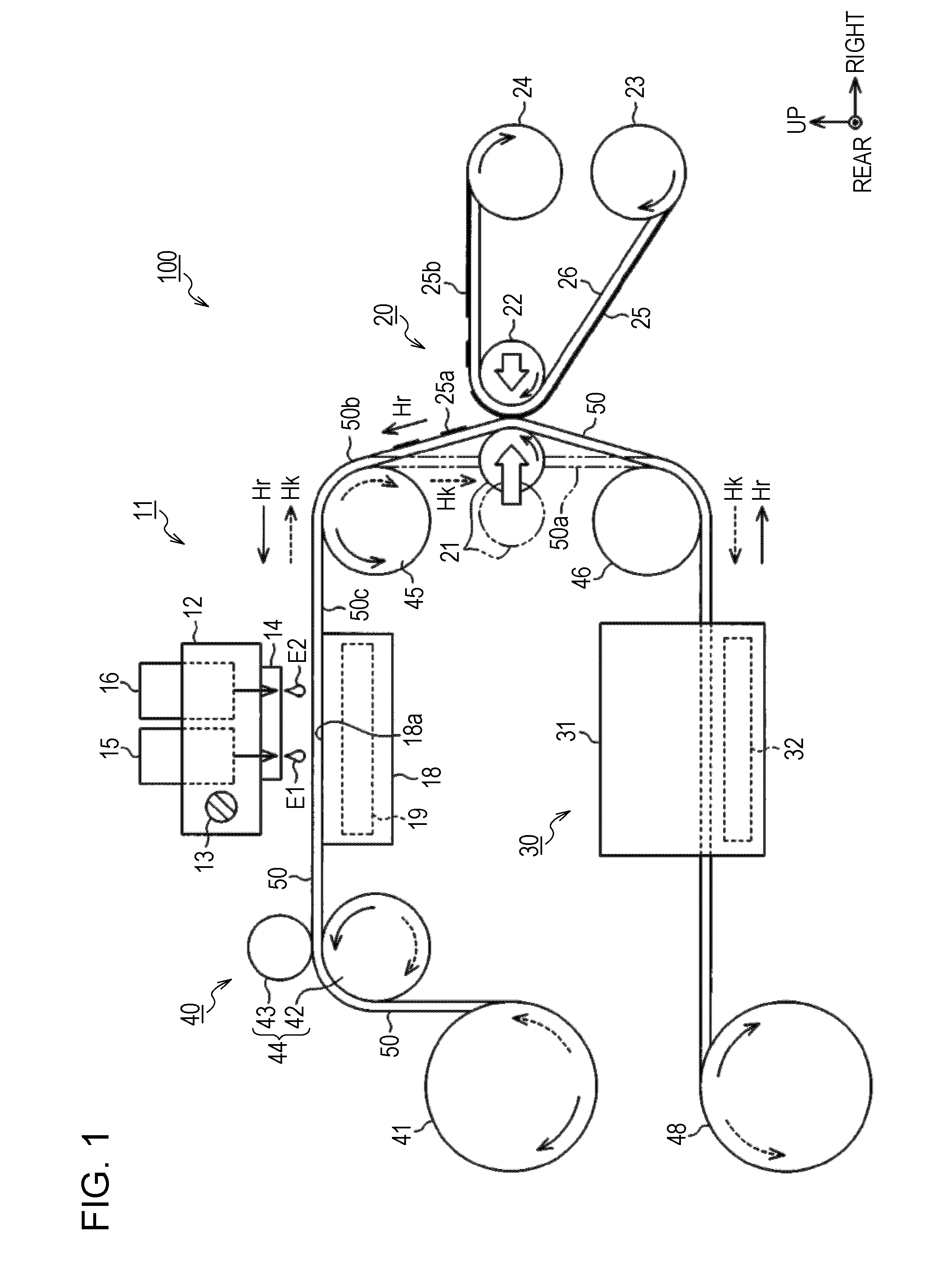
[0031]An embodiment of a laminated foil manufacturing apparatus to which the invention is embodied is described with reference to the drawings. In the following description, “front-rear direction”, “right-left direction”, and “up-down direction” indicate front-rear direction, right-left direction, and up-down direction which are indicated by arrows in the drawings, respectively. Note that in FIG. 1, the up-down direction corresponds to the vertical direction and the right-left direction corresponds to the horizontal direction intersecting with the up-down direction. Further, the front-rear direction is a direction intersecting with both of the up-down direction and the right-left direction and corresponds to the direction in which a carriage 12 reciprocates, that is, the scanning direction.

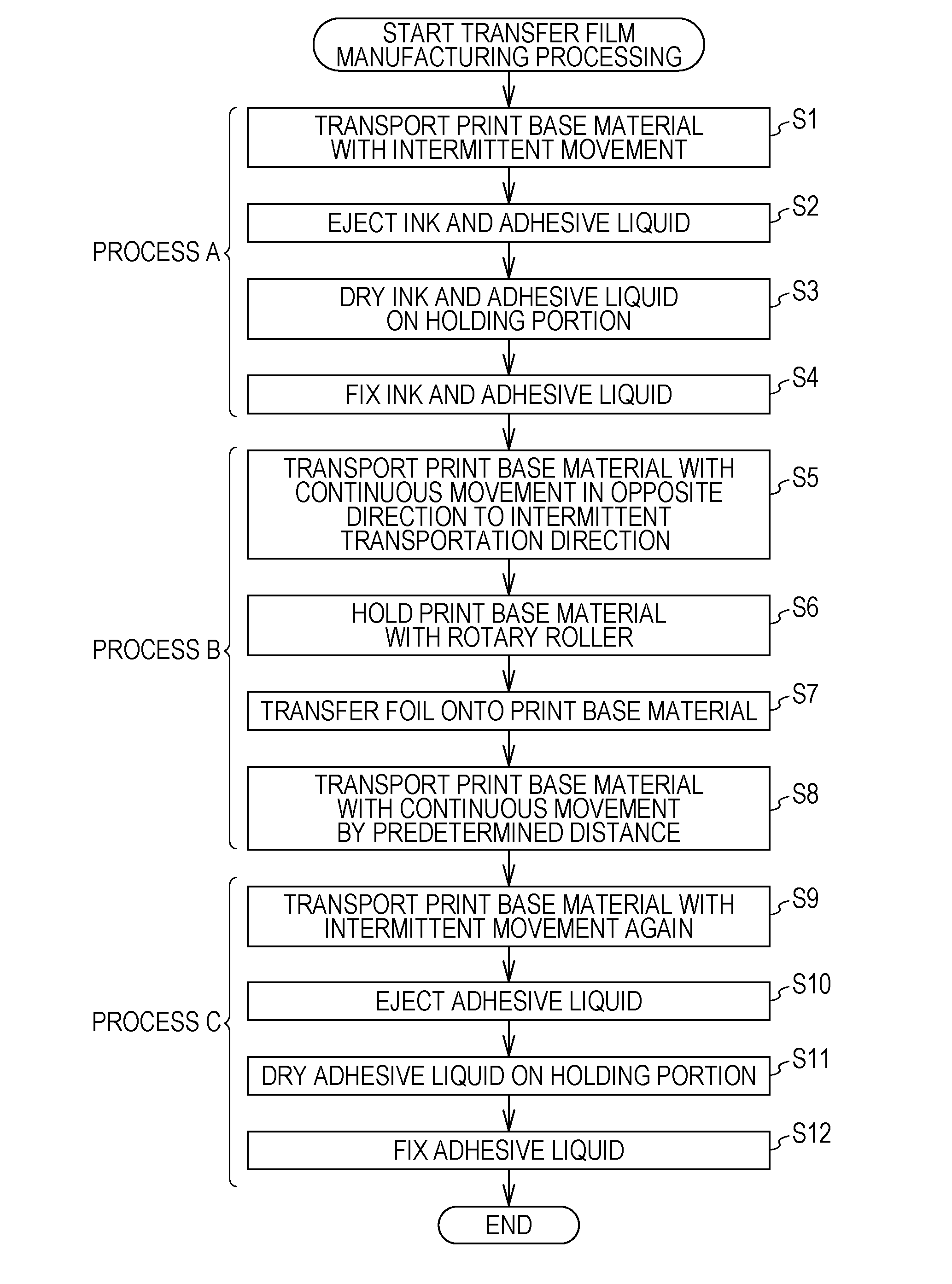
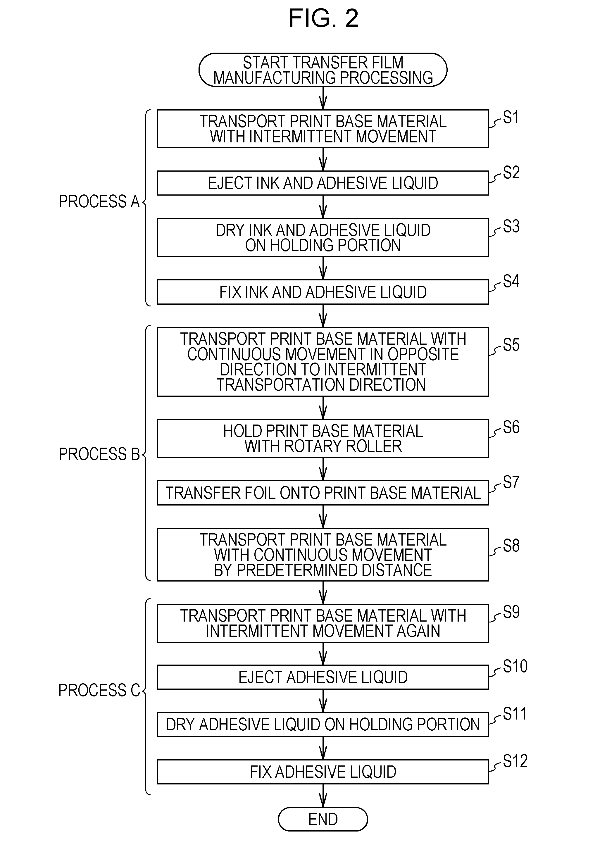
[0032]As illustrated in FIG. 1, a laminated foil manufacturing apparatus 100 includes a liquid adhering unit 11 and a foil laminating unit 20. The liquid adhering unit 11 performs adhering process...


PUM

PropertyMeasurementUnit
Widthaaaaaaaaaa

Abstract

A laminated foil manufacturing apparatus includes a transportation unit that transports a lamination target medium onto which foil is to be laminated with intermittent movement and continuous movement, a liquid adhering unit that performs adhering processing of making liquid adhere to the lamination target medium which is transported with the intermittent movement by the transportation unit, and a foil laminating unit that is arranged at a downstream side with respect to a position of the liquid adhering unit in a transportation direction of the lamination target medium which is transported with the intermittent movement, and performs foil laminating processing of laminating the foil onto a surface to which the liquid has been adhered on the lamination target medium which is transported with the continuous movement by the transportation unit after the adhering processing has been performed.

Description

BACKGROUND[0001]1. Technical Field[0002]The present invention relates to a laminated foil manufacturing apparatus and a laminated foil manufacturing method.[0003]2. Related Art[0004]In an existing printed material obtained by printing an image on a film such as a transfer film, a laminating film, a packing film, or a label film, a print image is decorated in the following manner in order to enhance a decorative effect of the print image. That is, for example, aluminum foil or the like having metallic luster is laminated onto a film of a base material so as to form laminated foil. In recent years, a laminated foil manufacturing apparatus having a configuration which makes it possible to perform on-demand printing by using no printing plate has been proposed as an apparatus for manufacturing such laminated foil in a small lot at low cost.[0005]For example, an on-demand foil transfer printing apparatus has been disclosed in JP-A-2009-226863 as a laminated foil manufacturing apparatus. ...

Claims


Application Information

Patent Timeline
IPC IPC(8): B32B37/12
CPCB32B38/10B32B38/145B32B2037/243B32B2311/24Y10T156/10B44C1/162B44C1/17Y10T156/1744B32B2519/00
Inventor TAKEMOTO, KIYOHIKOTSUKIANA, KAZUAKIOHASHI, MASAKAZU
Owner SEIKO EPSON CORP
Why Eureka
Try Eureka