Bi-stable shock absorber assembly

a shock absorber and bi-stable technology, applied in the direction of shock absorbers, liquid based dampers, vibration dampers, etc., can solve the problems of fast response of devices and very little energy, and achieve the effect of very little energy and cheap manufacturing

Inactive Publication Date: 2013-01-03
BEIJINGWEST INDUSTRIES
View PDF21 Cites 72 Cited by
  • Summary
  • Abstract
  • Description
  • Claims
  • Application Information

AI Technical Summary

Benefits of technology

[0007]The present invention is for a shock absorber assembly including a fluid for absorbing forces between a first component and a second component. The shock absorber assembly includes a valve engaging a piston for impeding the passage of fluid through an aperture in the piston. A bi-stable solenoid is disposed in the housing and is interconnected with the valve. The bi-stable solenoid features an armature that is moveable between a first stable position for applying a first biasing force against the valve and a second stable position for applying a second biasing force being less than the first biasing force against the resilient disc of the valve (or vice and versa). Adjusting the biasing force on the valve also adjusts the damping force of the shock absorber. Thus, the operator of the vehicle has the ability to choose between a hard (high force) damping setting (with the solenoid's armature in the first stable position) and a soft (low force) damping setting (with the solenoid's armature in the second stable position). The damping setting can be switched between the high and low settings on the fly with the simple flip of a switch.
[0008]The subject shock absorber assembly is also advantageous when compared to the prior art. Generally, the device's response is fast and it consumes very little energy. Specifically, all that is required to adjust the shock absorber from the high force damping setting to the low force damping setting is a short pulse of electrical current. Another short pulse of (reversed) electrical current reverts the shock absorber back to the high force damping setting. Advantageously, a constant supply of current is not required to maintain the bi-stable solenoid in either of the stable positions.
[0009]Also advantageously, the bi-stable solenoid system is compact and fits within the housing of the shock absorber. With minor adjustments to the geometry of the housing, the shock absorber can be installed onto any pre-existing suspension system. The bi-stable solenoid also latches very strongly into the first and second stable positions. Therefore, the shock absorber assembly is resistant to undesirable and accidental damping settings changes.
[0010]Moreover, the valve and bi-stable solenoid can be used in combination with other valving controls for adjusting the damping force of the shock absorber. Finally, no sophisticated controls are required to adjust the damping setting of the shock absorber. All that is required to adjust the damping force of the shock absorber assembly is a short pulse of electrical current generated in such a way to cancel the latching force of the bi-stable solenoid assembly. Thus, the shock absorber can be manufactured cheaply without the need for an expensive and complicated controller.

Problems solved by technology

Generally, the device's response is fast and it consumes very little energy.

Method used


Image

  • Bi-stable shock absorber assembly
  • Bi-stable shock absorber assembly
  • Bi-stable shock absorber assembly

Examples


Embodiment Construction

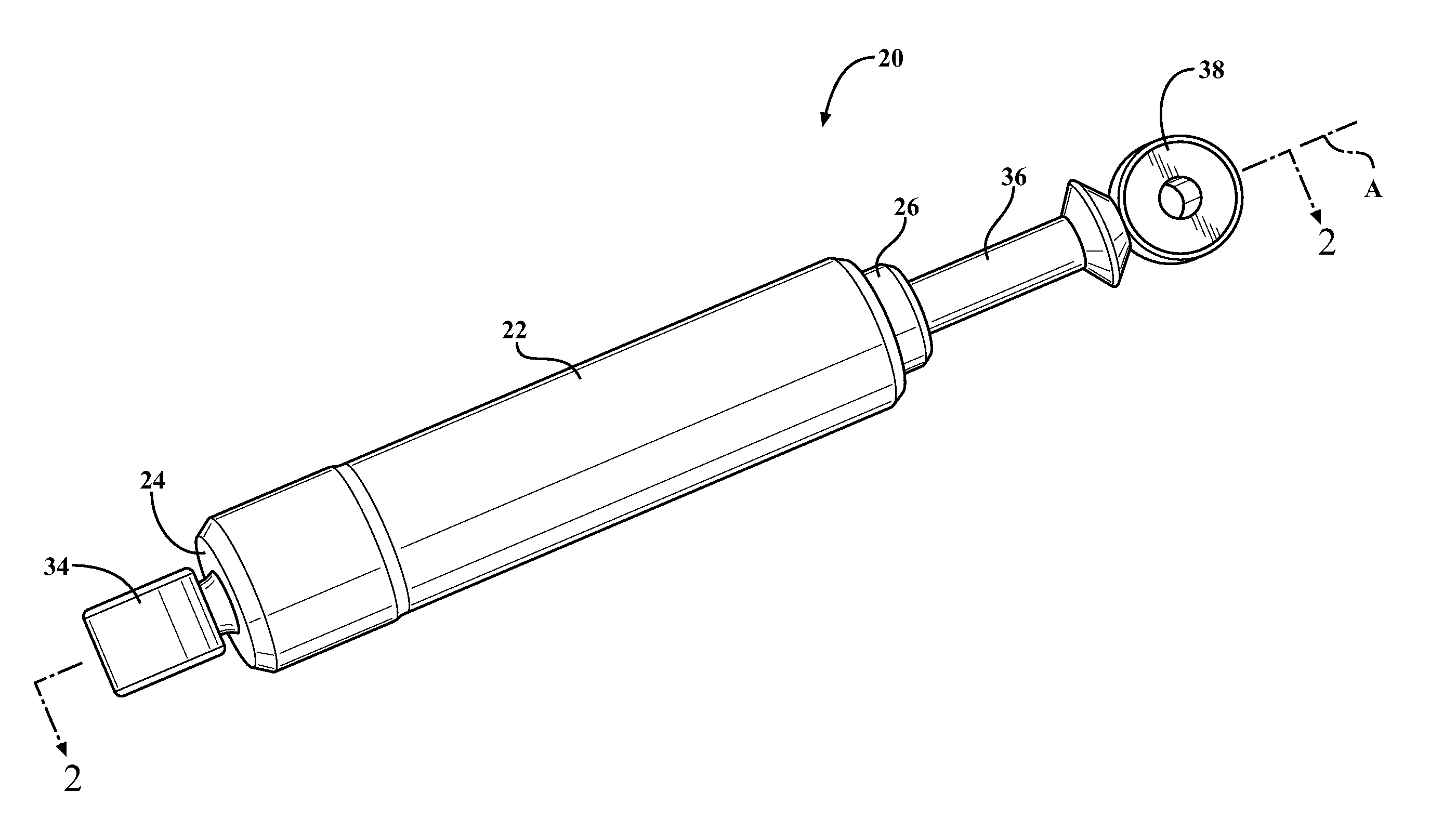
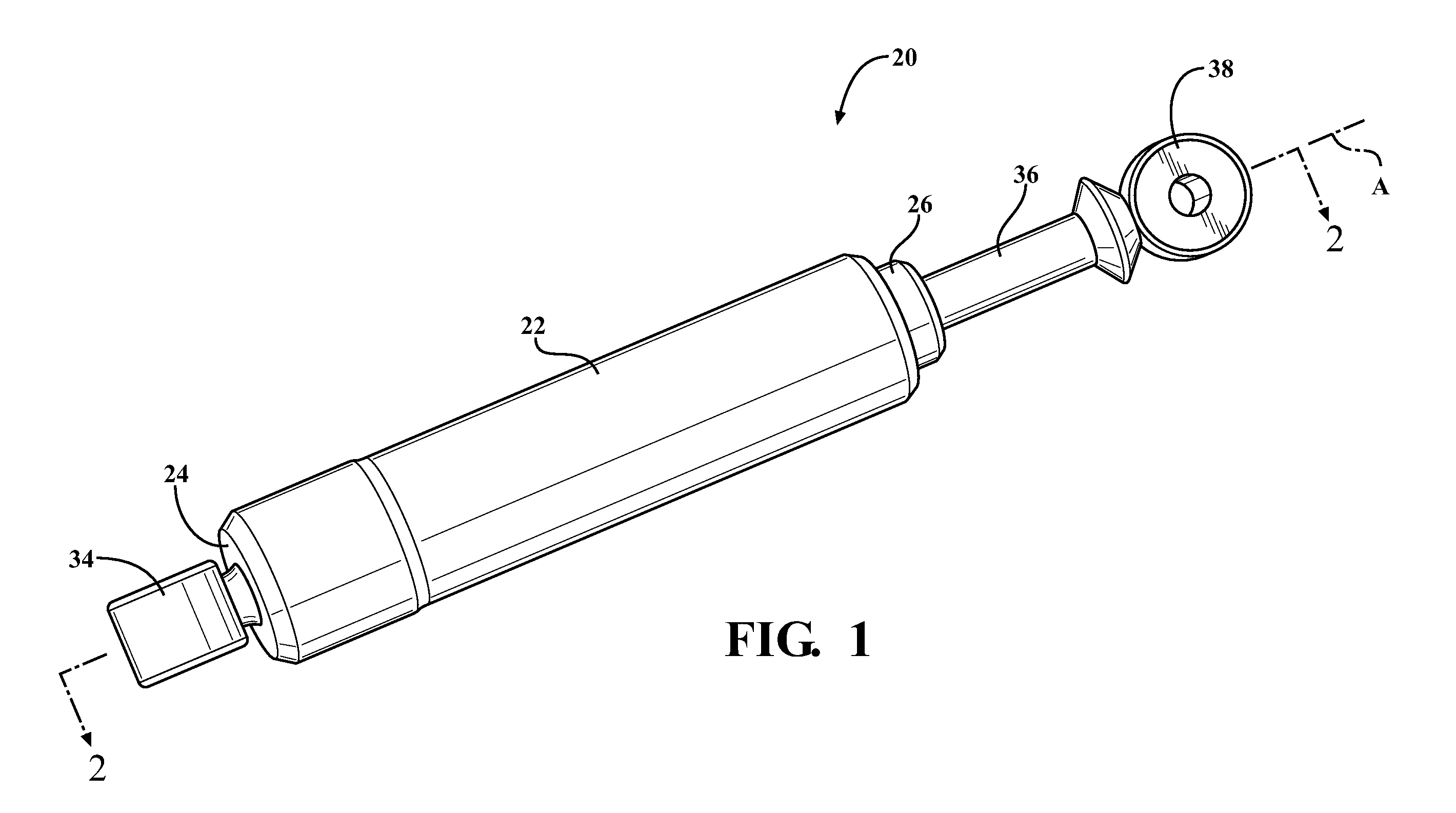
[0016]Referring to the Figures, wherein like numerals indicate corresponding parts throughout the several views, a shock absorber assembly 20 for absorbing forces between a first component and a second component is generally shown in FIG. 1. Although shown in the drawings as being a mono-tube shock absorber, it should be appreciated that all of the exemplary embodiments could be used in a twin-tube shock absorber. The shock absorber could be used in many different applications, including but not limited to a motor vehicle, an all-terrain vehicle, or a snowmobile.

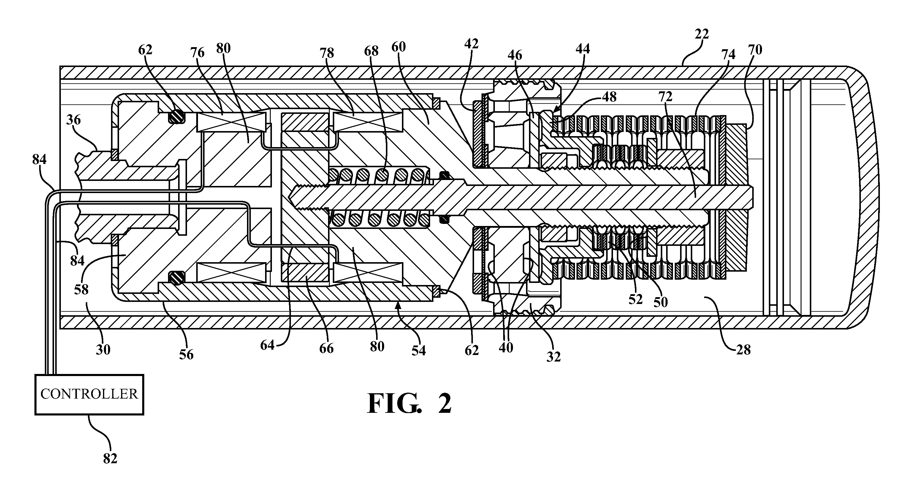
[0017]FIG. 2 is a cross-sectional view of a first exemplary embodiment of the shock absorber assembly 20. The first exemplary embodiment includes a housing 22 having a cylindrical shape and extending along an axis A from a first housing end 24 to a second housing end 26 and presenting an open interior 28, 30. An oil is preferably disposed in the interior of the housing 22, though any other fluid may alternatively be used.

[00...


PUM


Abstract

A shock absorber assembly including a fluid for absorbing forces between the body and the wheel of a motor vehicle. The shock absorber includes a valve having a resilient disc engaging a piston for impeding the passage of fluid through the aperture of the piston. A bi-stable solenoid is disposed in the housing and is interconnected with the resilient disc of the valve. The bi-stable solenoid's armature is moveable between a first stable position for applying a first biasing force against the resilient disc of the valve and a second stable position for applying a second biasing force being less than the first biasing force against the resilient disc of the valve. The adjustment of the biasing force on the valve also adjusts the damping force of the shock absorber.

Description

CROSS REFERENCE TO RELATED APPLICATIONS[0001]This application claims priority to International Patent Application No. PCT / US2010 / 057777 filed on Nov. 23, 2010, entitled “Bi-Stable Solenoid Shock Absorber Assembly” and U.S. Provisional Application No. 61 / 263,513 filed on Nov. 23, 2009 entitled “Hydraulic Damper”.BACKGROUND OF THE INVENTION[0002]1. Field of the Invention[0003]A shock absorber assembly including a fluid for absorbing forces between a first component and a second component[0004]2. Description of the Prior Art[0005]Motor vehicles generally include a suspension system having a shock absorber, also known as a damper, for absorbing forces between the frame and the wheel assembly of the vehicle. Most shock absorbers have a cylindrically shaped housing extending along an axis and presenting an open interior. A piston is slidably disposed in the housing to divide the open interior into a compression chamber on one side of the piston and a rebound chamber on the other side of t...

Claims


Application Information

Patent Timeline
Patent Type & Authority Applications(United States)
IPC IPC(8): F16F9/50F16F9/348F16F9/19
CPCF16F9/464F16F2222/06
Inventor GOLDASZ, JANUSZNEHL, THOMAS W.
Owner BEIJINGWEST INDUSTRIES
Why Eureka
Try Eureka