Surface treatment system and workpiece-holding jig

a surface treatment system and workpiece technology, applied in the field of surface treatment systems, can solve the problems of unnecessary moment, impaired commercial value of workpieces, and complex structure of feed rails, so as to improve the surface treatment quality of workpieces and improve the uniformity of the current distribution of workpieces in the plan

Active Publication Date: 2013-01-03
ALMEX PE INC
View PDF2 Cites 17 Cited by
  • Summary
  • Abstract
  • Description
  • Claims
  • Application Information

AI Technical Summary

Benefits of technology

[0114]According to the above configuration, it is possible to improve the in-plane uniformity of the current distribution of the workpiece, and further improve the surface treatment quality of the workpiece due to the effects achieved by (5) and (14).

Problems solved by technology

On the other hand, when disposing the feed rail at a position offset from a position above the plating tank (see Japanese Patent No. 3591721), the center of gravity of the transfer jig and the workpiece is offset from the perpendicular line that passes through the feed rail, so that an unnecessary moment acts on the transfer jig.
Therefore, the structure of the feed rail also becomes complex.
If the workpiece is tilted to intersect the transfer direction when viewed from above when the workpiece that is held by the transfer jig advances in the treatment solution, the workpiece may be bent due to the treatment solution, so that the commercial value of the workpiece may be impaired.
If a vertical motion of the transfer jig occurs when the workpiece that is held by the transfer jig advances in the treatment solution, the electrical contact between the feed rail and the transfer jig may be impaired, so that the plating quality may deteriorate.
It was also found that it is difficult to ensure the in-plane uniformity of the surface treatment of the workpiece when providing only a current-carrying path that is connected to the upper side (end) of the workpiece (see JP-A-2009-132956).

Method used


Image

  • Surface treatment system and workpiece-holding jig
  • Surface treatment system and workpiece-holding jig
  • Surface treatment system and workpiece-holding jig

Examples


Embodiment Construction

)

[0135]Exemplary embodiments of the invention are described in detail below. Note that the following exemplary embodiments do not in any way limit the scope of the invention defined by the claims laid out herein. Note that all elements of the following exemplary embodiments should not necessarily be taken as essential elements of the invention.

1. Outline of Surface Treatment System

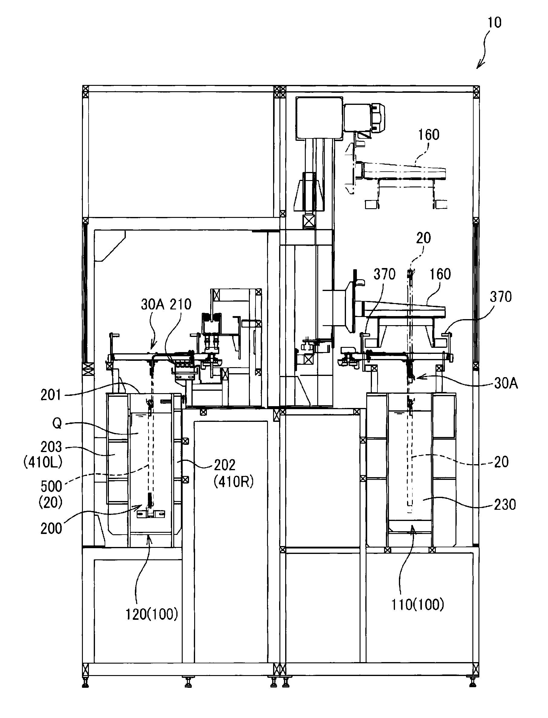
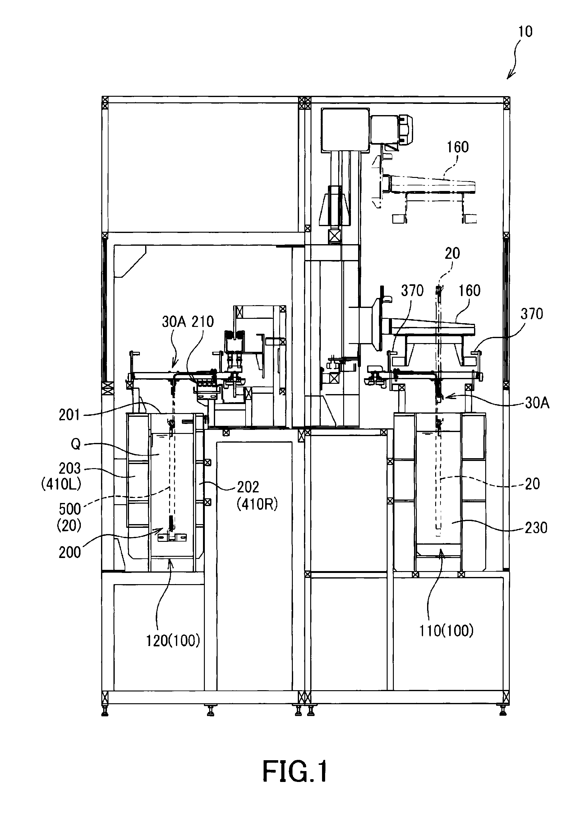
[0136]FIG. 1 is a vertical cross-sectional view illustrating a surface treatment system (e.g., serial (continuous) plating system). A serial plating system 10 illustrated in FIG. 1 is configured so that a plurality of transfer jigs 30A that respectively hold a workpiece 20 (e.g., circuit board) are transferred (circulated) in the direction perpendicular to the sheet. FIG. 1 illustrates two linear transfer paths 110 and 120 that form a circulating transfer path 100 and are parallel to each other. The linear transfer paths 110 and 120 are connected at both ends to form the loop-like circulating transfer path...


PUM

PropertyMeasurementUnit
currentaaaaaaaaaa
current distributionaaaaaaaaaa
currentaaaaaaaaaa

Abstract

A surface treatment system includes a surface treatment tank, a first guide rail and a second guide rail that extend at a position offset from a position over the upper opening of the surface treatment tank, and a plurality of transfer jigs that respectively hold a workpiece and are supported by the first guide rail and the second guide rail. The transfer jig includes a horizontal arm section, a first guide target section that is guided by the first guide rail, a second guide target section that is guided by the second guide rail, and a vertical arm section that is suspended from the horizontal arm section at a position between the first guide target section and the second guide target section, and holds the workpiece.

Description

BACKGROUND OF THE INVENTION[0001]1. Field of the Invention[0002]The present invention relates to a surface treatment system (e.g., serial (continuous) plating system) and a workpiece-holding jig.[0003]2. Description of the Related Art[0004]A serial plating system that serially (continuously) transfers workpieces (e.g., circuit boards) in a plating tank has been known as a surface treatment system such as an electroplating system that plates the surface of a workpiece. The workpiece is suspended from a transfer jig that is transferred along a feed rail, and serially transferred in the plating tank while current is supplied to the workpiece from the feed rail via the transfer jig. Anodes are disposed in the plating tank on either side of a transfer path of the workpiece (i.e., cathode). An electric field is formed between the cathode and the anode to electrolyze the plating solution and plate the surface of the workpiece.[0005]A structure has been known in which the feed rail extends ...

Claims


Application Information

Patent Timeline
Patent Type & Authority Applications(United States)
IPC IPC(8): C25D17/08C25D17/02
CPCB65G49/0477C25D17/005C25D17/06B05C3/09B05C3/10B05C3/02C25D17/02C25D17/08C25D17/28
Inventor NODA, TOMOHIROWATANABE, SHIGEYUKIISHII, KATSUMI
Owner ALMEX PE INC
Why Eureka
Try Eureka