

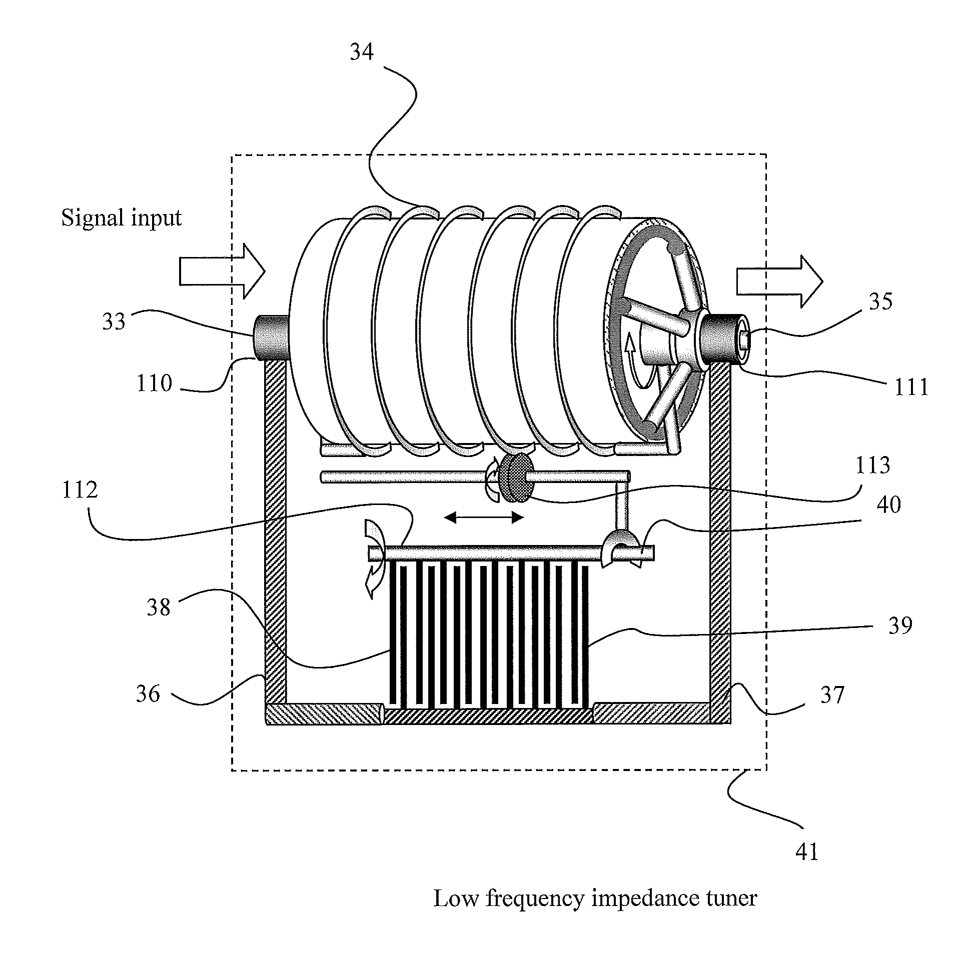
Wideband low frequency impedance tuner
a low frequency impedance and tuner technology, applied in waveguide devices, delay lines, waveguide types, etc., can solve the problems of inability to inherently wideband the solution, and inability to achieve wideband coverag
- Summary
- Abstract
- Description
- Claims
- Application Information
AI Technical Summary
Benefits of technology
Problems solved by technology
Method used
Image

Examples
Embodiment Construction
[0048]The wideband MHz range impedance tuner comprises, in its simplest form (FIG. 7), one linear phase shifter (92) between test or input port (12) and idle or output port (13); and one variable capacitor (15), which is connected to said linear phase shifter using some sliding galvanic contact (14). Changing the position of said sliding contact (14) along the transmission line of said linear phase shifter creates a section X and a section L-X, assuming the total length of said transmission line to be L. Following the concept of the microwave slide screw impedance tuner, the electrical length of the in-line phase shifter has to be at least one half a wave-length at the lowest operation frequency. As we have seen before, the electrical length in air, required at 10 MHz is 15 meters and at 1 MHz it is 150 meters. There is no way such dimensions can be accommodated in a laboratory environment, if a linear approach is adopted.
[0049]The alternative approach described in this invention co...
PUM
 Abstract
Description
Claims
Application Information