Rf-link margin measurement method and system

a technology of rflink margin and measurement method, which is applied in the field of electronic toll collection system, can solve the problems of unreliable and possibly no communication with some vehicle/transponder combination, affecting the localization accuracy, and negatively affecting the communication link between the reader and the transponder

Active Publication Date: 2013-01-03
KAPSCH TRAFFICCOM AG
View PDF6 Cites 7 Cited by
  • Summary
  • Abstract
  • Description
  • Claims
  • Application Information

AI Technical Summary

Problems solved by technology

A too high RF margin may cause undesired “cross-lane” reads whereby a transponder is triggered in an adjacent lane, which may affect the localization accuracy.
On the other hand, an RF margin that is too low results in unreliable and possibly no communication with some vehicle/transponder combinations.
Over time, the RF margin can change (it typically decrease

Method used


Image

  • Rf-link margin measurement method and system
  • Rf-link margin measurement method and system
  • Rf-link margin measurement method and system

Examples


Embodiment Construction

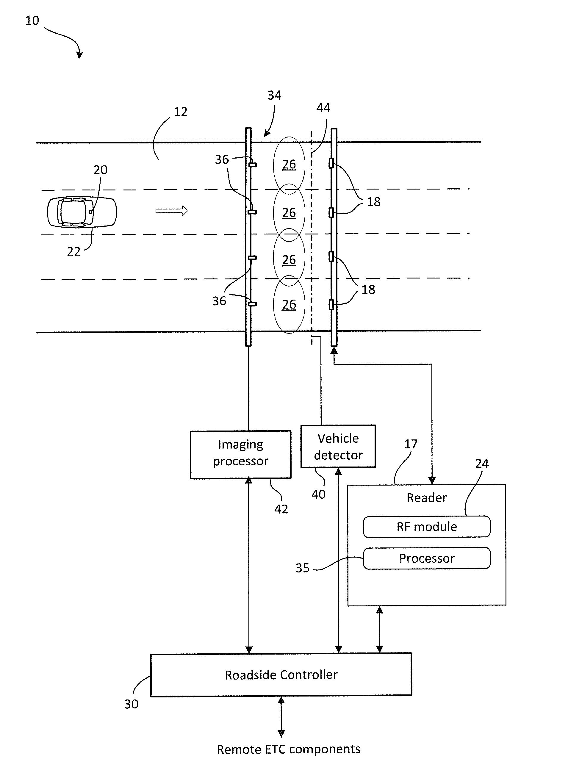
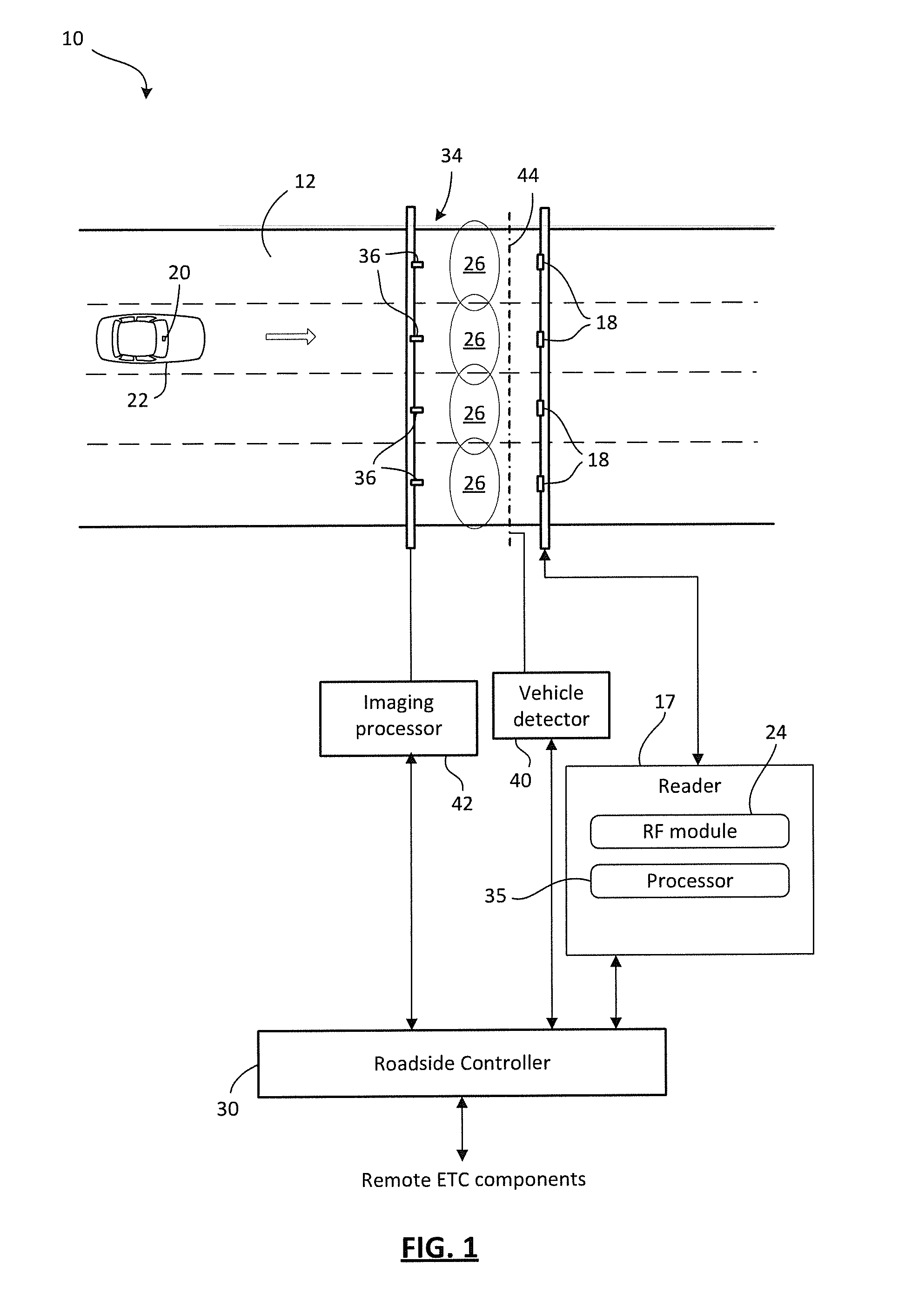
[0023]Reference is first made to FIG. 1, which in a block diagram form shows an exemplary electronic toll collection (ETC) system 10, according to some embodiments of the present invention. The ETC system 10 is employed in connection with a roadway 12 having one or more lanes for vehicular traffic. The arrow in the roadway 12 indicates the direction of travel. For diagrammatic purposes, a vehicle 22 is illustrated in the roadway 12. In some instances, the roadway 12 may be an access roadway leading towards or away from a toll highway. In other instances, the roadway 12 may be the toll highway itself.

[0024]Vehicle 22 is shown in FIG. 1 with a transponder 20 mounted to the windshield. In other embodiments, the transponder 20 may be mounted in other locations. For example, it may be mounted on or near the license plate area of the front bumper area of the vehicle.

[0025]The ETC system 10 includes antennas 18 connected to an automatic vehicle identification (AVI) reader 17. The reader 17...


PUM


Abstract

A system and method for conducting dynamic RF-link margin tests in an electronic toll collection for non-stationary vehicles travelling up to highway speed. The system maintains a list of candidate transponders and, during the course of a normal toll collection, if a transponder is on the list then the system schedules a margin test for a later handshake in the capture zone. At a location at or near the peak margin test the system conducts a margin test during one or more of the reader-transponder handshakes. The attenuation may be dynamically controlled by the system using a variable attenuator in the RF path from the reader RF module to the antenna. Distributing the margin measurement over multiple passes of a vehicle through the capture zone provides for a highway speed method of measuring link margin.

Description

CROSS-REFERENCE TO RELATED APPLICATION(S)[0001]This application claims priority to Canadian Patent Application No. 2,744,625, filed on Jun. 28, 2011, the contents of which are hereby expressly incorporated by reference.FIELD OF THE INVENTION[0002]The present application relates to electronic toll collection (ETC) systems and, in particular, to a method and system for measuring RF-link margin in an ETC system.BACKGROUND OF THE INVENTION[0003]In Electronic Toll Collection (ETC) systems, Automatic Vehicle Identification (AVI) is achieved by the use of Radio Frequency (RF) communications between roadside readers and transponders within vehicles. Each reader emits a coded identification signal, and when a transponder enters into communication range and detects the reader, the transponder sends a response signal. The response signal contains transponder identification information, including a unique transponder ID. In the United States, current AVI RF communication systems are licensed un...

Claims


Application Information

Patent Timeline
IPC IPC(8): H04Q5/22
CPCG07B15/063G07B15/02G07B15/00
Inventor TERRIER, DANIEL
Owner KAPSCH TRAFFICCOM AG
Why Eureka
Try Eureka