Unlock instant, AI-driven research and patent intelligence for your innovation.

Imaging lens

a technology of chromatic aberration and lens, applied in the field of imaging lenses, can solve the problems of insufficient small aberration achievement, inconvenient downsizing, and inability to achieve small aberrations, etc., and achieve the effect of effective correction of chromatic aberration, large aperture ratio, and high performan

Active Publication Date: 2013-01-03
TOKYO VISIONARY OPTICS CO LTD
View PDF1 Cites 11 Cited by
  • Summary
  • Abstract
  • Description
  • Claims
  • Application Information

AI Technical Summary

Benefits of technology

The present invention aims to provide an imaging lens that is small, can correct chromatic aberration effectively, correct various aberrations satisfactorily, has a large aperture ratio, and is high-performing, to match the slimming trend of recent cellular phones.

Problems solved by technology

Inevitably, imaging lenses fixed to the imaging devices are also subjected to intense demands for downsizing.
As the performance required for the imaging lens corresponding to such imaging element, the simple accomplishment of small aberrations is not enough.
In Patent document 1, the total track length (TTL) is long, so that it is not suitable for downsizing.
Further, it is difficult to realize favorable aberration correction while securing large aperture ratio.
Patent document 2 and Patent document 3 propose practical lenses by solving the problems of the four-lens configuration, however, it is disadvantageous in cutting down costs since a large number of lenses must be used to configure the imaging lens.
Further, since a large number of lenses sensible to manufacturing tolerance is used, it is disadvantageous also from the viewpoint of manufacturing cost.
Also, since glass material is heavily used, it is disadvantageous from the viewpoint of reducing cost.
Further, in Patent document 2 and Patent document 3, when plastic material is selected for decreasing cost, since the applicable lens material is extremely limited, it is difficult to achieve both correction of chromatic aberration and correction of other various aberrations.

Method used


Image

  • Imaging lens
  • Imaging lens
  • Imaging lens

Examples


embodiment 1

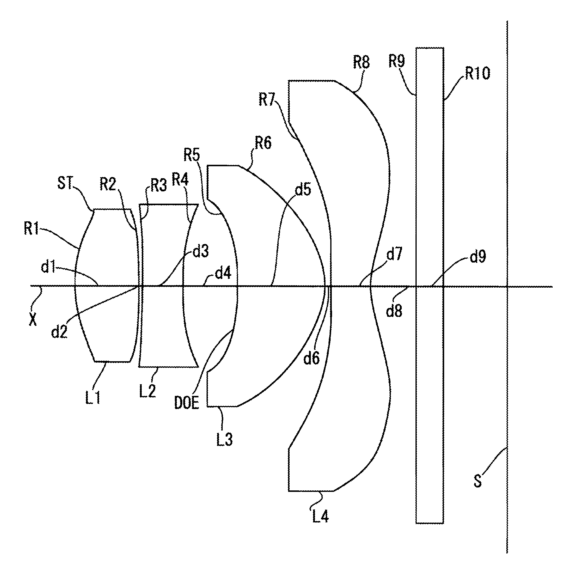
[0049]The basic lens data is shown in Table 1 below. The diffraction optics surface DOE is formed on the surface R5 of the third lens L3 on the object side.

TABLE 1Surface dataSurface No.RdnvObject surface∞∞ 1 (diaphragm)1.57500.70001.5369056.1 2−6.20590.0394 3−9.36600.44191.6198825.4 43.63060.6077 5 (DOE)−2.34700.96021.5464755.8 6−0.74200.0682 7−31.00000.43491.5369056.1 80.87120.5000 9∞0.30001.5187264.010∞0.7076Image surface∞f = 3.905, Fno = 2.4, ω = 36.4°

[0050]Next, Table 2 shows the aspheric coefficient and the values of each coefficient of the optical path difference function of the diffraction optics surface in embodiment 1.

TABLE 2Aspheric surface dataFirst surfaceSecond surfaceAspheric coefficientAspheric coefficientK = −5.0322E+00K = 0.0000E+00A4 = 1.5537E−01A4 = 1.5010E−01A6 = −1.3886E−01A6 = −5.1353E−01A8 = 1.5429E−01A8 = 2.7025E−01A10 = −1.5617E−01A10 = 0.0000E+00Third surfaceFourth surfaceAspheric coefficientAspheric coefficientK = 2.5754E+01K = −4.6191E−01A4 = 2.0551E−01A...

embodiment 2

[0055]The basic lens data is shown in Table 3 below. Similar to embodiment 1, the diffraction optics surface DOE is formed on the surface R5 of the third lens L3 on the object side in embodiment 2.

TABLE 3Surface No.RdnvObject surface∞∞ 1 (diaphragm)1.49480.69211.5369056.1 2−6.17210.0348 3−6.19000.34191.6198825.4 44.20690.6659 5 (DOE)−2.00090.98741.5464755.8 6−0.75910.1184 7−39.05060.40001.5369056.1 80.91660.5000 9∞0.30001.5187264.010∞0.7196Image surface∞f = 3.945, Fno = 2.4, ω = 36.1°

[0056]Next, Table 4 shows the aspheric coefficient and the values of each coefficient of the optical path difference function of the diffraction optics surface in embodiment 2.

TABLE 4Aspheric surface dataFirst surfaceSecond surfaceAspheric coefficientAspheric coefficientK = −7.0303E+00K = 0.0000E+00A4 = 2.5117E−01A4 = 1.9275E−01A6 = −2.7772E−01A6 = −5.9949E−01A8 = 3.0853E−01A8 = 3.2689E−01A10 = −2.3573E−01A10 = 0.0000E+00Third surfaceFourth surfaceAspheric coefficientAspheric coefficientK = 0.0000E+00K ...

embodiment 3

[0060]The basic lens data is shown in Table 5 below. In embodiment 3, the diffraction optics surface DOE is formed on the surface R3 of the second lens L2 on the object side.

TABLE 5Surface No.RdnvObject surface∞∞ 1(diaphragm)1.98900.68481.5369056.1 2−6.50000.1075 3(DOE)−54.99990.55061.6198825.4 43.91590.5259 5−2.09100.75971.5369056.1 6−0.84650.1384 7−100.00000.49881.5369056.1 81.07070.6945 9∞0.30001.5187264.010∞0.5000Image surface∞f = 3.918, Fno = 2.4, ω = 36.3°

[0061]Next, Table 6 shows the aspheric coefficient and the values of each coefficient of the optical path difference function of the diffraction optics surface in embodiment 3.

TABLE 6Aspheric surface dataFirst surfaceSecond surfaceAspheric coefficientAspheric coefficientK = 2.0524E+00K = 0.0000E+00A4 = −6.4874E−02A4 = −1.2081E−01A6 = −8.3277E−02A6 = 8.0359E−03A8 = 1.5937E−02A8 = 1.0148E−02A10 = −5.4916E−02A10 = 0.0000E+00Third surfaceFourth surfaceAspheric coefficientAspheric coefficientK = 0.0000E+00K = −3.2492E+01A4 = 1.319...


PUM


Abstract

To provide a high image-quality, low cost, and small sized imaging lens suitable for an imaging lens which is compact and which has high density pixels, and with aberrations corrected satisfactorily. An imaging lens is configured from a first lens, a second lens, a third lens, and a fourth lens arranged in the named order from an object side, wherein both surfaces of each lens are formed from aspheric surface, and a diffraction optics surface exerting chromatic aberration correction function is arranged on any one surface from a surface of the first lens on an object side to a surface of the third lens on the object side, and each lens is configured from plastic material.

Description

[0001]The present application is based on and claims priority of Japanese patent application No. 2011-146649 filed on Jun. 30, 2011, the entire contents of which are hereby incorporated by reference.BACKGROUND OF THE INVENTION[0002]1. Field of the Invention[0003]The present invention relates to an imaging lens which forms on an imaging element such as a CCD (Charge Coupled Device) sensor or a CMOS (Complementary Metal Oxide Semiconductor) sensor an image of an object, and relates to a small-sized imaging lens to be mounted on a PDA (Personal Digital Assistant) such as a cellular phone and the like.[0004]2. Description of the Related Art[0005]In recent years, camera functions are mounted on almost all cellular phones. Recently, cellular phones with high-resolution camera function comparable with a digital still camera mounted thereon have been introduced. Imaging devices realizing such camera function are being downsized further in accordance with increasing demands for downsizing an...

Claims


Application Information

Patent Timeline
Patent Type & Authority Applications(United States)
IPC IPC(8): G02B13/18
CPCG02B13/004
Inventor SUZUKI, HISANORIMATSUOKA, KAZUO
Owner TOKYO VISIONARY OPTICS CO LTD