
Utility pole

a technology of utility poles and poles, applied in the field of utility poles, can solve the problems of too many roadside poles, serious damage to vehicles, and injury to the occupants of impacting vehicles

Inactive Publication Date: 2013-01-10
GRIFFITHS MICHAEL +1
View PDF23 Cites 23 Cited by
  • Summary
  • Abstract
  • Description
  • Claims
  • Application Information

AI Technical Summary

Benefits of technology

The invention describes a hollow body with a flange on the outside to help position the top section correctly. This makes it easier to assemble the parts.

Problems solved by technology

An impact of a vehicle with a utility pole can result in serious damage to the vehicle, and can also result in injury to the occupants of the impacting vehicle.
Mostly, such roadside poles are left exposed to impacts with vehicles, however when poles are particularly badly located with respect to likelihood of vehicles striking them, a common practice is to use a guardrail so as to direct a vehicle around the pole.
There are, however, currently perceived to be too many roadside poles for this to be a practical economical solution.
Some of the drawbacks of this approach are that after breaking away, the heavy poles can fall back onto the vehicle, potentially causing serious injury to the vehicle occupants, or can gain energy from the vehicle impact and be thrown forward so as to potentially cause significant injury to other road users.
Another potential problem is that where the utility pole is supporting electricity cables, the cables can break and fall onto the impacting vehicle, the roadway or other road users.
Cables carrying high voltage electricity can represent a considerable danger to road users.

Method used


Image

  • Utility pole
  • Utility pole
  • Utility pole

Examples


Embodiment Construction

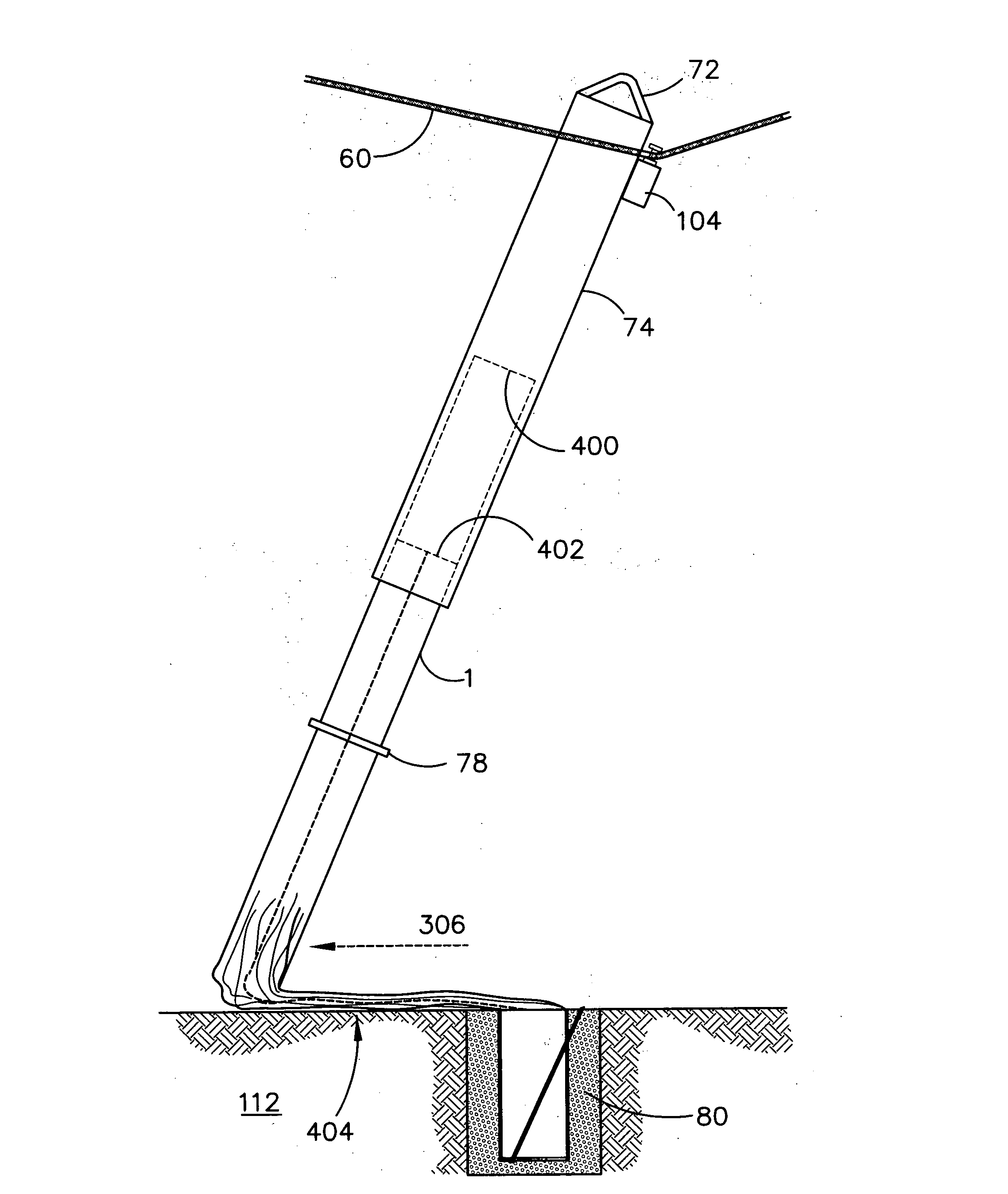
[0064]The utility poles described herein are designed to crush and absorb energy or to break away in a controlled manner when struck by a vehicle. The intended result is to extend the distance over which the impacting vehicle comes to a stop so as to significantly reduce the forces on the vehicle experienced by the occupants. As a consequence this reduces the likelihood of injury resulting from a crash involving the utility pole.

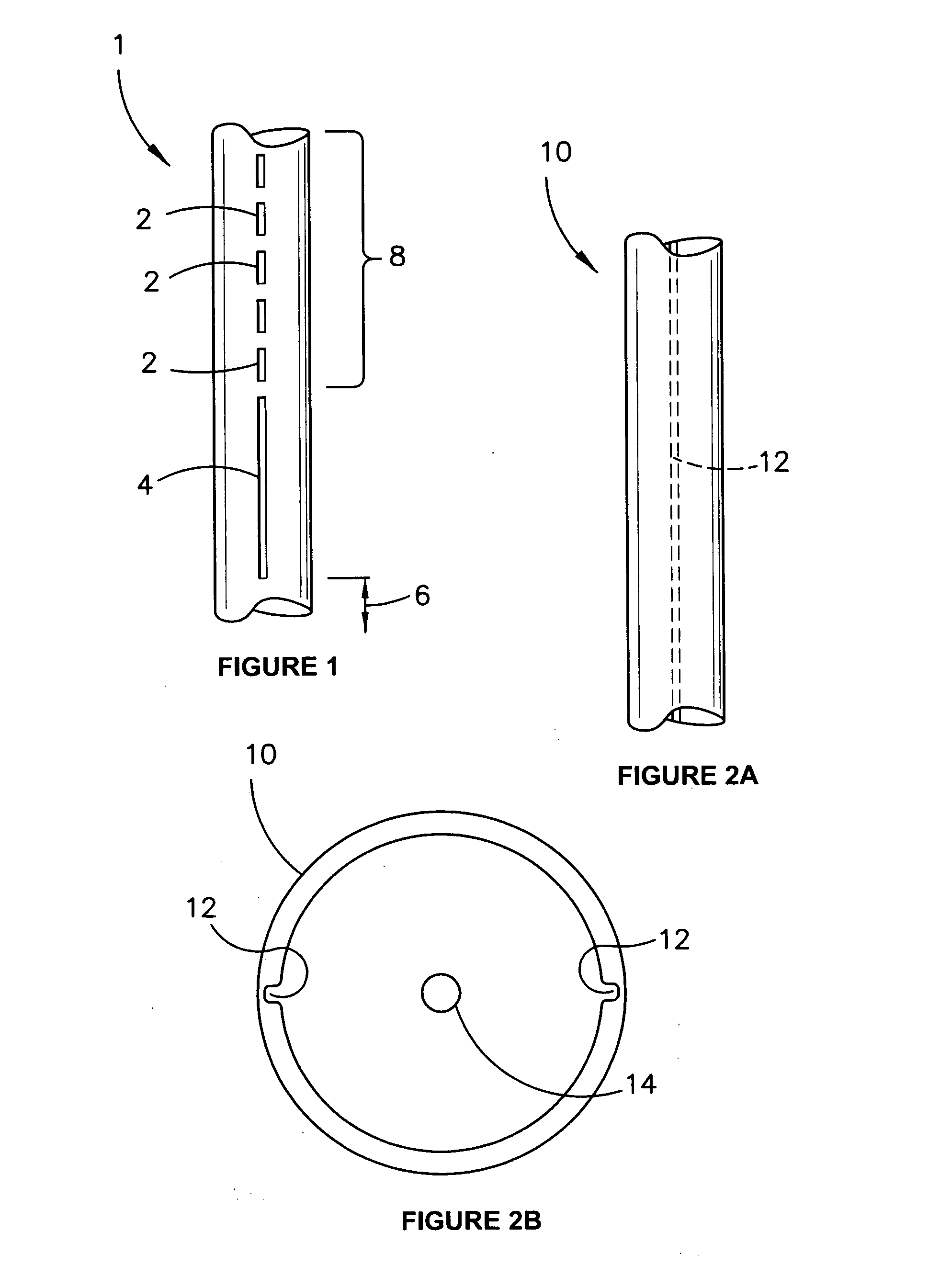
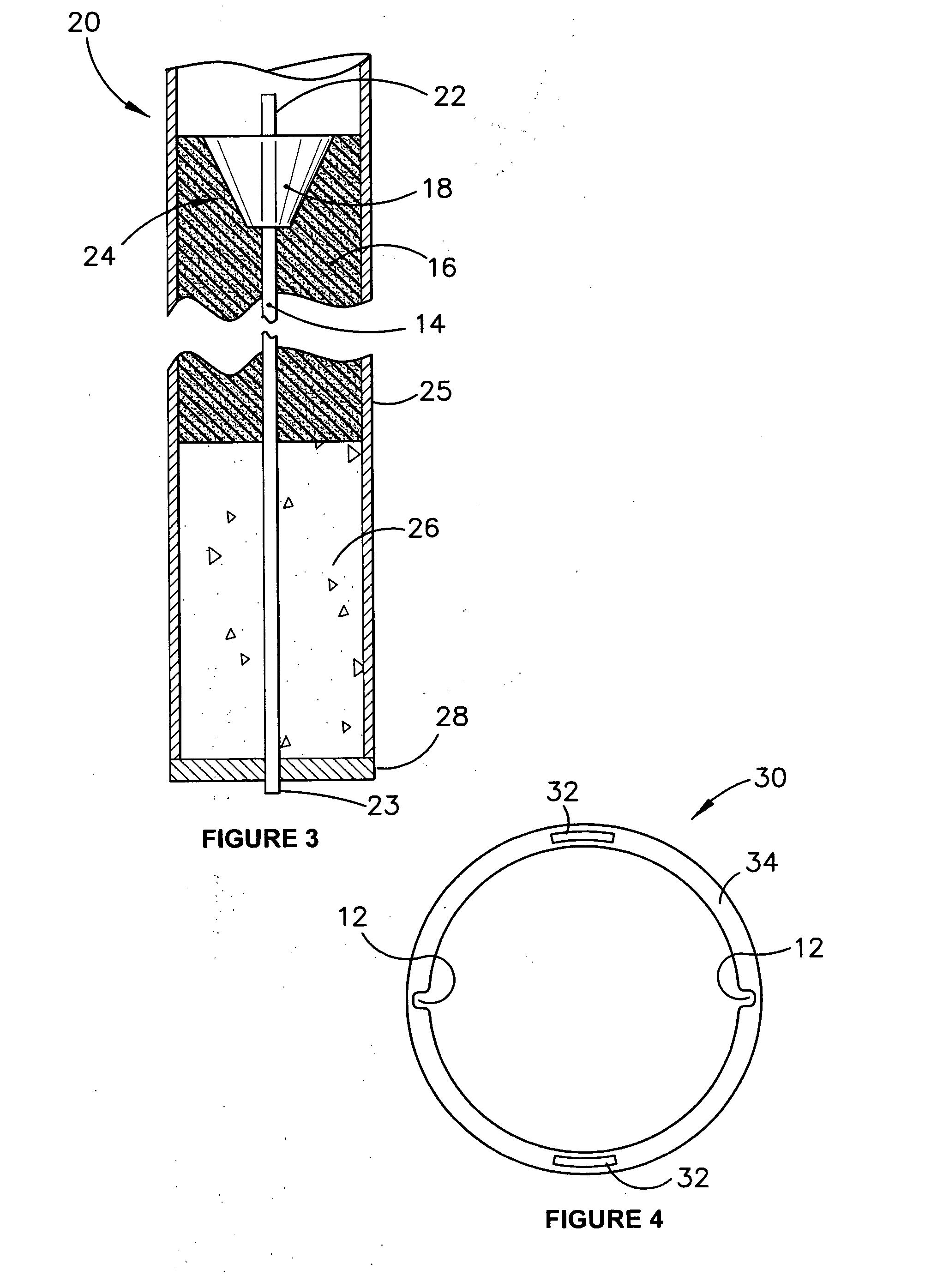
[0065]FIG. 1 shows a portion of a utility pole 1 that is manufactured using a composite material. The material provides a pole that is light compared with traditional materials such as wood or metal. The composite material is typically a combination of fibres and a matrix such as a resin, where most of the tensile strength of the composite material is provided by the reinforcing fibres and most of the compressive strength is provided by the solidified matrix. The fibres can be carbon, graphite, Kevlar™, fibreglass or some other suitable fibre that provides t...


PUM


Abstract

A utility pole comprises a hollow elongate body (1) formed from a composite material including reinforcing fibres embedded in a matrix material and an energy-absorbing region comprising at least one elongate weakened zone (2, 4, 12) formed in the hollow elongate body (1), the at least one weakened zone promoting delamination of the fibres and the matrix material if a vehicle strikes the utility pole.

Description

FIELD OF THE INVENTION[0001]The present invention relates to utility poles, and in particular to utility poles with enhanced safety features.BACKGROUND OF THE INVENTION[0002]Utility poles, which are traditionally made of timber, metal or concrete, support signs, traffic signals, lighting systems or the like and are often located close to roadways. An impact of a vehicle with a utility pole can result in serious damage to the vehicle, and can also result in injury to the occupants of the impacting vehicle.[0003]Mostly, such roadside poles are left exposed to impacts with vehicles, however when poles are particularly badly located with respect to likelihood of vehicles striking them, a common practice is to use a guardrail so as to direct a vehicle around the pole. There are, however, currently perceived to be too many roadside poles for this to be a practical economical solution.[0004]One possible solution is to design poles that break away from the base during heavy impact from a ve...

Claims


Application Information

Patent Timeline
IPC IPC(8): H02G7/00E02D27/42E01F9/018H01B17/14E04H12/24
CPCE01F9/0182E01F9/635
Inventor GRIFFITHS, MICHAELJARVIE, JOHN MICHAEL
Owner GRIFFITHS MICHAEL
Learn More