Method and device for strengthening and lightening floor and roof framing

a technology for strengthening and lightening floor and roof, applied in the field of construction, can solve the problems of reducing the absorption and loading capacity of the system, reinforcing rods, and difficulty in placing the mesh in the proper place, and achieves the effects of increasing the loading capacity of the framing, enhancing the shear stress absorption, and simple and low cos

Inactive Publication Date: 2013-01-10
SIMON DOMINGUEZ JAVIER ANTONIO
View PDF12 Cites 9 Cited by
  • Summary
  • Abstract
  • Description
  • Claims
  • Application Information

AI Technical Summary

Benefits of technology

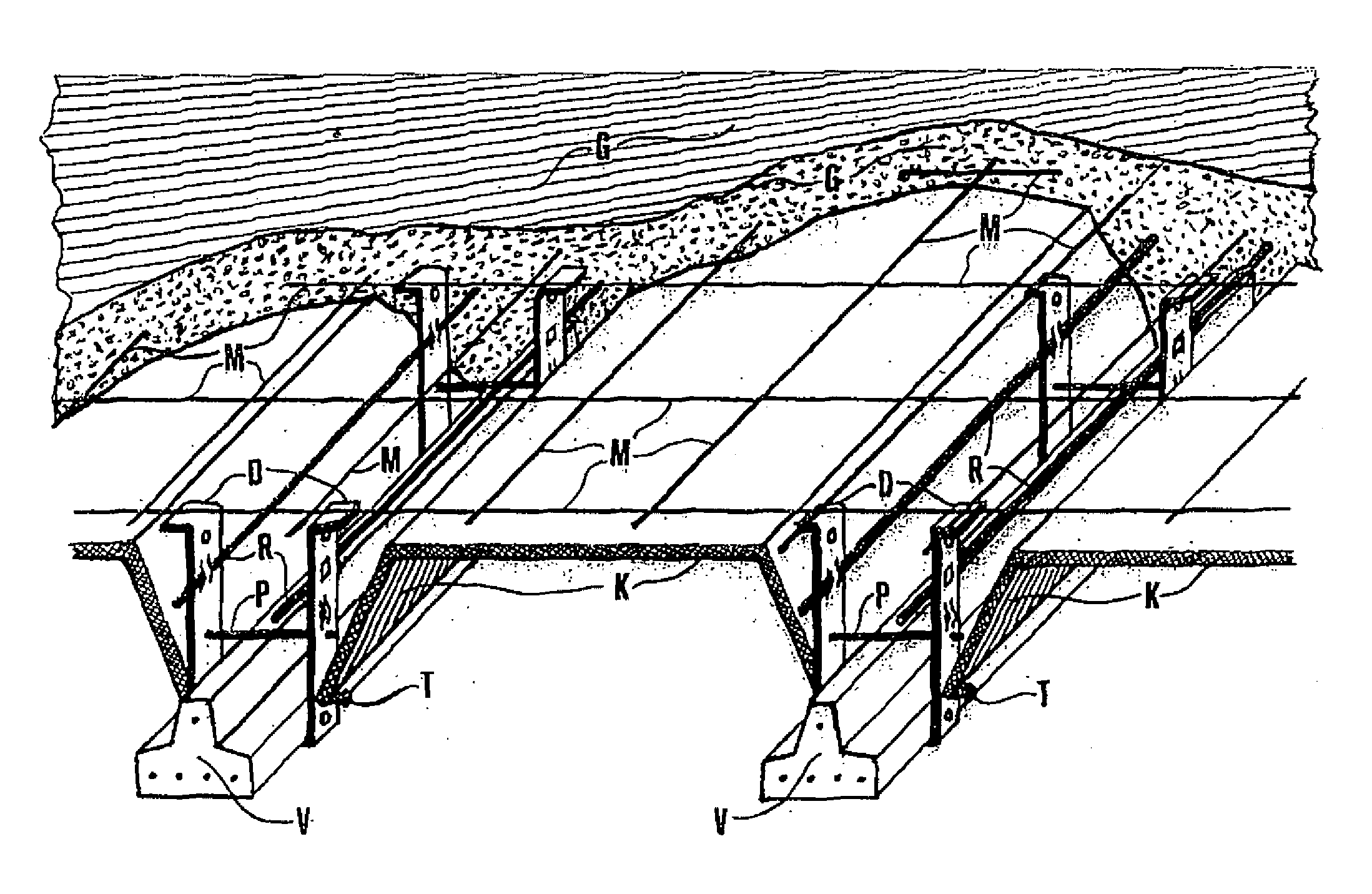
[0003]The present invention applies in the technical field of construction, mainly in floor and roof framing of reinforced concrete, it is related to a procedure and to a simple and low cost device, capable of being adapted to all kind of prefabricated beams, using also; moulds, mesh, concrete laid on site, and if necessary, reinforcing rods. With this invention, a framing is achieved wherein the compression slab and beams are firmly integrated, increasing the loading capacity of the framing, enhancing the shear-stress absorption, allowing that bigger spaces in longitudinal direction to the beams be covered, making easier to properly place the mesh and reinforcing rods, if required. The invention allows making it possible to easily recover the moulds for re-use, lightening the framing, and therefore reducing the necessary requirements for the walls or girders wherein the framing is seated, notably reducing the related costs. The device lower section non-covered with concrete remains available for the affixation of supports for ducts, ceiling roses, or any other suitable item without requiring drilling the framing.

Problems solved by technology

In said framings, the ruptures and cracks are very frequent due to the weak adherence between the smooth beam surfaces and the concrete forming the compression slab, thus impeding a suitable incorporation to work together, decreasing the absorption of the shear-stress and the loading capacity of the system.
Also in these procedures it is difficult to place the mesh in the proper place, and if necessary, reinforcing rods.
In many of these cases, the use of blocks of concrete which are encased in the system, add an excessive weight with a practically null structural benefit.
And if after to the setting of the framing, to firmly affix supports for ceiling roses, ducts, lamps, it is required, then it is necessary to drill it, taking the risk of damaging it.

Method used


Image

  • Method and device for strengthening and lightening floor and roof framing
  • Method and device for strengthening and lightening floor and roof framing
  • Method and device for strengthening and lightening floor and roof framing

Examples


Embodiment Construction

[0010]Method and device for strengthening and lightening floor and roof framing.

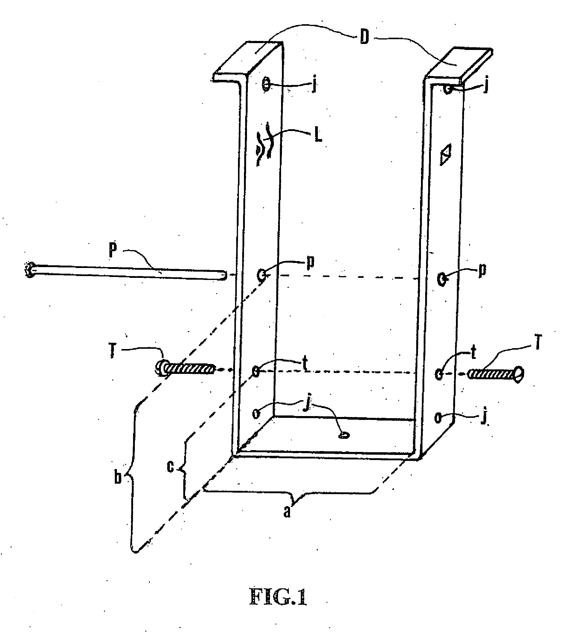
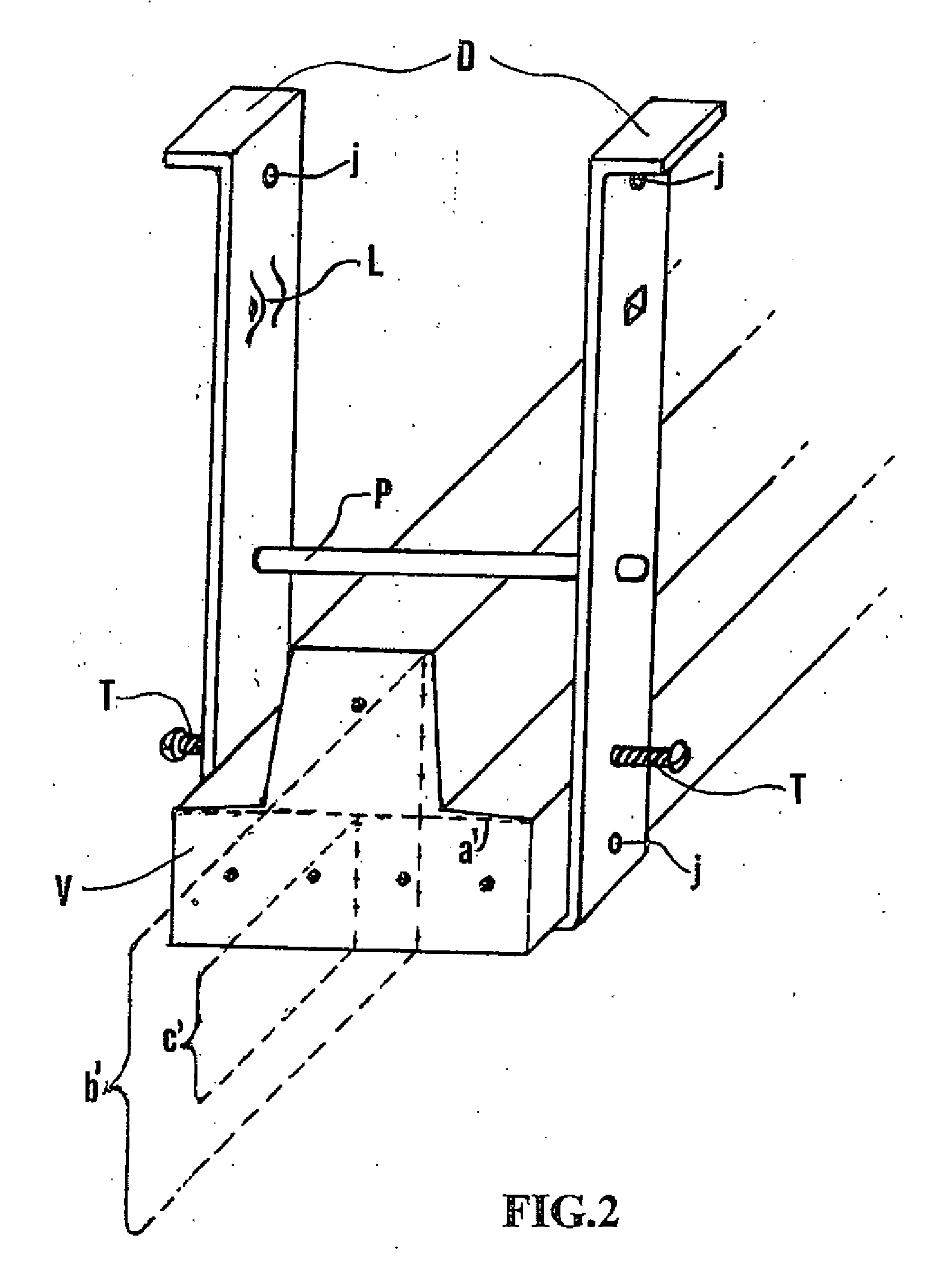
[0011]Wherein the method uses mainly some devices, prefabricated beams (V), moulds (K), mesh (M), concrete laid on site (C), and if necessary, reinforcing rods (R). The method is characterized by preferably starting transversally installing a device in the beam, the device consisting of a profile, a pin (P) and two screws (T), wherein the profile is made from a tensile-strength resistant material, preferably folded into a “U” shape, conformed according to the used beam (V), the lower section of the profile having in its inner wall, the shape and dimensions of the base and adjacent sides of the beam cross-section (V), when the profile sides reach the level where the beam cross-section has its higher width (a′), said sides are perpendicularly extended to its base plane, wherein the spacing between each other (a) is equal to the maximum width (a′) of the beam cross-section, said sides continue until reachin...


PUM


Abstract

Method and device for strengthening and lightening floor and roof framing, where the beams and the compression slab are firmly integrated, making it possible to easily recover the moulds or blocks lightening the framing. The method uses several devices, prefabricated beams, moulds, mesh, concrete laid on site and where necessary reinforcing rods. The devices comprise essentially: a section, two bolts and a pin. The section will be tensile-stress resistant and folded into a “U” shape to match the beams. The method involves affixing the device, wrapped transversally around the beam. Likewise, and several devices can be affixed along each beam. The beams are then placed on their walls or girders, parallel and separated depending on the moulds, then the moulds are seated in the protruding segments of the bolts of the device until the spans are covered, affixing reinforcing rods in the sides of the device where necessary. The mesh is then laid by attaching it to the ends of the devices. The concrete is then poured until the compression slab and the channels above the beams are filled. Once set, the bolts are removed to recover the moulds from below.

Description

FIELD OF THE INVENTION[0001]The present invention is applied in the technical field of construction, mainly for the framing of floor and roof of reinforced concrete in buildings, houses, bridges, or in constructions general.BACKGROUND OF THE INVENTION[0002]Nowadays many procedures for the manufacture of floor and roof framing of reinforced concrete are based on placement on the walls and girders, prefabricated beams placed parallel and separated to each other, such that when the blocks or moulds seat on their sides, the spans between the beams are covered, then a mesh is placed in a parallel plan exceeding the blocks, the concrete is then poured on the whole in order to form the compression slab. In said framings, the ruptures and cracks are very frequent due to the weak adherence between the smooth beam surfaces and the concrete forming the compression slab, thus impeding a suitable incorporation to work together, decreasing the absorption of the shear-stress and the loading capaci...

Claims


Application Information

Patent Timeline
Patent Type & Authority Applications(United States)
IPC IPC(8): E04B5/32E04G21/02
CPCE04G11/44E04B5/261E01D19/12E01D21/00E04G11/46E04G11/48E04G17/02E04G17/04E04G17/18
Inventor SIMON-DOMINGUEZ, JAVIER ANTONIO
Owner SIMON DOMINGUEZ JAVIER ANTONIO
Why Eureka
Try Eureka