Tuning peg for a stringed instrument

a technology for stringed instruments and tuning pegs, which is applied in the direction of stringed musical instruments, instruments, music aids, etc., can solve the problems of comparatively large space required for tuning pegs, complicated attainment of string ends on tuning pegs, and inability to detune instruments, etc., to achieve a high degree of positional precision and stability, no associated risk, and easy fixation

Inactive Publication Date: 2013-01-10
GOODBUY CORP
View PDF3 Cites 4 Cited by
  • Summary
  • Abstract
  • Description
  • Claims
  • Application Information

AI Technical Summary

Benefits of technology

[0010]With a tuning peg designed in a manner according to the invention, the end of a string that is to be fixed therein and adjusted in terms of its tension and tuning can not only be easily fixed, whereby a corresponding longitudinal section of the free end of the string is arranged on the abutment section and clamped there by means of a clamping element that can be displaced on the tuning peg along the retaining section. In so doing, the string end can be clamped with a high degree of positional precision and stability so that unlike traditional methods, there is no risk that the knot will yield or that the attachment will come loose and therefore there will be no resulting detuning of the string fixed there. Due to the fact that the string is clamped along a longitudinal section, and thus a section of the string's length that is significantly different than what is selectively clamped at a single point is clamped between the abutment section and the clamping element, the clamping forces are distributed along a greater area of the string. As a result, there are no load peaks, so there is no associated risk of breaking or tearing a string.
[0011]A circumferential collar in particular, is suitable as an abutment section. This circumferential collar extends around the axis of the tuning peg and serves as a support for a section of the string end that is routed around a substantial portion of the circumference (up to nearly 360°) of the axis of the tuning peg, and this entire length of string can then be clamped my means of the clamping element. Therefore, in the event that the installation space is very small, such a circumferential collar also offers the possibility of clamping the string end over a substantial length, and thus distributing the clamping forces over a wider section of the string. In addition to the aforementioned reduction of load peaks, this also results in an improved grip, since clamping, and therefore the clamping and frictional forces, is distributed over a greater section of the string.
[0012]A circumferential collar within the meaning of this solution, is also understood as a collar that is intermittently interrupted along the circumference of the tuning peg, for example featuring one or more recesses, as is specified in claim 4, in particular. Such a recess can be used, for example, to pass the end of the string from one side of the collar, on which, for example, the winding section may be situated (see claim 3) to the opposite side, where the collar features the abutment surface and on which, for example, the retaining section may be situated (see claim 3), without having to make an especially sharp bend in the string when passing the same over the edge of the collar. Comparatively gently curved radii can be formed when passing the string end from one side of the collar, through a recess as a duct, through to the winding section, which, in turn, benefits the durability of the string, in which acute angular directional changes always constitute a weak point, especially if there is friction due to the vibrating string.
[0013]According to a further advantageous embodiment of the invention, the retaining section may be an externally threaded section of the tuning peg and the clamping element may be a screw element with internal thread that corresponds to the aforementioned external thread. A solution of this kind makes the tuner especially easy to use, and in addition, a suitable selection of the thread pitch and the remaining design aspects of the external and internal thread can securely lock the external thread and the internal thread in position, in which the clamping element presses against the string adjacent to the abutment and holds it on the basis of the clamping force.
[0014]It is particularly advantageous if the externally threaded section is arranged on a free end of the tuning peg in such a way that the screw element can be screwed onto the externally threaded retaining section such that it is completely removable from the tuning peg. This type of design allows for the particularly easy replacement and maintenance of parts. Naturally, it is also possible to design the screw element in such a way that it cannot be detached, or at least easily detached, from the externally threaded section of the tuning peg, for example in order to avoid the loss of the threaded clamping element should that element be inadvertently opened too far.
[0015]The screw is advantageously equipped with a knob section for easier handling, which, in particular, can be designed having a serrated, knurled or otherwise structured as a circumferential section having an otherwise profiled structure. Such knurled screws or screw elements that are otherwise provided with a grip profile simplify handling without the use of any tools.

Problems solved by technology

This method of fixing a string end on the tuning peg is complicated to achieve, and there is a risk that the string end will come loose or give way, thereby detuning the instrument, especially if the process is not carried out properly.
Furthermore, the knot or similar wound structure for fixing the string end takes up a considerable amount of space so that the space required for tuning pegs is comparatively large.
The aforementioned disadvantages affect, in particular, those tuning pegs that are motor-driven and adjust the string tension as a component in an automatic tuning system.
In so doing, it has been shown that not only were the forces needed to provide a secure grip substantial, but that the risk of breaking or tearing the string at the clamping point is also substantial due, in particular, to the high forces and the selective exertion of those forces on the string at a specific point.
In addition to the considerable cost incurred for a new instrument string, this is also a nuisance which represents a clear disadvantage to such attempts to fix the string in place.

Method used


Image

  • Tuning peg for a stringed instrument
  • Tuning peg for a stringed instrument
  • Tuning peg for a stringed instrument

Examples


Embodiment Construction

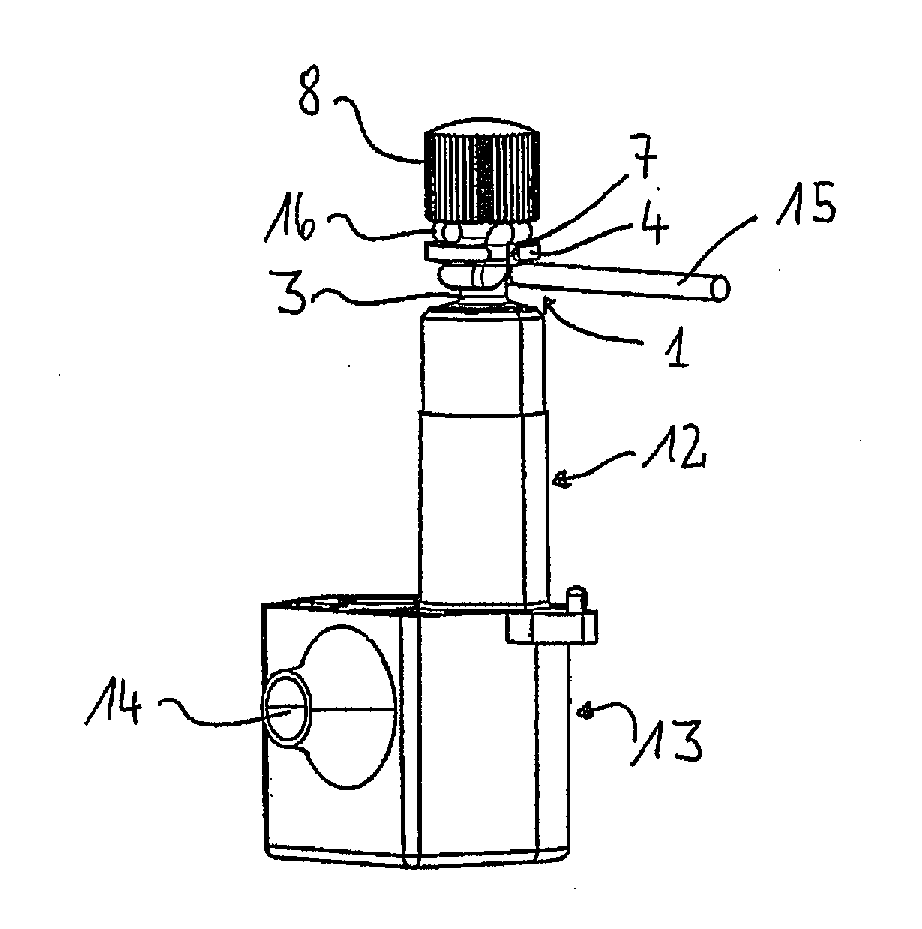
[0021]The figures show an embodiment of a tuning peg according to the invention that is a tuning peg for a guitar and, in particular, an electric guitar. The figures shown are purely schematic and do not represent complete structural design drawings. They serve merely to explain and describe an embodiment in order to further illustrate the invention.

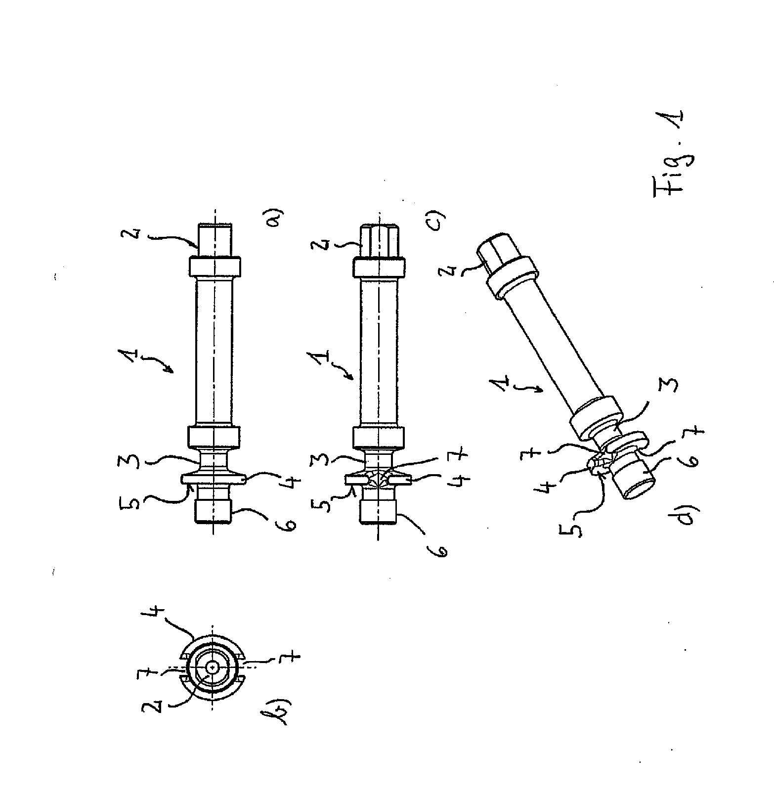
[0022]FIGS. 1a to 1d show four views of a tuning peg according to the invention without showing the clamping element that is a part of the fastening means for fixing the end of a string of a musical instrument. The tuning peg 1 is an elongated part that is, in technical terms, a shaft. On one of its longitudinal ends, it features a connecting section 2 for connecting the same to an adjustment mechanism, for example a manually driven gear for the rotational adjustment of the tuning peg 1.

[0023]Moreover, the tuning peg 1 features a winding section 3 onto which a string of the musical instrument can be wound, or from which this string can b...


PUM


Abstract

A tuning peg for a stringed instrument, in particular a guitar, having a winding section, on which a string runs and a fastening means for fixing a free end of the string. To this end, a tuning peg according to the invention comprises a clamping element and, on the tuning peg, an abutment section and a retaining section. The retaining section and clamping element are set up such that the clamping element is displaced axially on the tuning peg along the retaining section and locked in a clamping position. The clamping element and abutment section are set up such that that they clamp and retain a longitudinal section of the free end of the string between them.

Description

TECHNICAL FIELD[0001]The present invention relates to a tuning peg for a stringed instrument and to a stringed instrument equipped with a tuning peg according to the invention.[0002]Tuning pegs in the case of stringed instruments refer to the rotating wooden pegs or metal pins on which the string ends are rolled up. These pegs can be used to modify the tension of the strings and thereby tune the instrument. For example, on guitars or violins, these tuning pegs are arranged on the so-called heads. In the case of modern guitars, the tuning pegs can be adjusted with proper handling through gear stages in order to be able to carry out fine tuning.[0003]Tuning pegs are thus shafts, in the technical sense, on which a string end is wound in order to tighten the string and thereby raise the tuning, or unwound in order to loosen the string and thereby lower the tuning.PRIOR ART[0004]In order to fix a string to a tuning peg, the tuning peg typically features a continuous bore hole or a slot i...

Claims


Application Information

Patent Timeline
Patent Type & Authority Applications(United States)
IPC IPC(8): G10D3/14
CPCG10D3/14G10D3/00G10G7/00
Inventor ADAMS, CHRISTOPHER
Owner GOODBUY CORP
Why Eureka
Try Eureka