Determination method, storage medium and information processing apparatus

Active Publication Date: 2013-01-10
CANON KK
View PDF19 Cites 6 Cited by
  • Summary
  • Abstract
  • Description
  • Claims
  • Application Information

AI Technical Summary

Benefits of technology

The present invention provides a method for determining the exposure conditions of an exposure apparatus by setting the parameters for the light intensity distribution and aberration of the illumination and projection optical systems. The method ensures that the image performance of the mask pattern meets the evaluation criteria for the target pattern. This invention is useful in accurately exposing a substrate during the manufacturing process.

Problems solved by technology

However, due to some error factors during exposure, the mask pattern is often transferred to a position deviated from the desired position in a shape deviated from the desired shape.
Examples of the error factors include the amount of exposure and the focus position in exposing the substrate.
Examples of factors which cause the focus position to deviate from an ideal state include instability of the position at which the substrate is held, and unevenness of the substrate.
Also, the aberration of the projection optical system is one of the above-mentioned error factors.
However, the capability of the aberration adjusting mechanism has a given limit, so the projection optical system generally has residual aberrations.
Therefore, if simply adjusting the effective light source shape and the mask pattern is insufficient to compensate for the influence that the aberration of the projection optical system exerts on the image performance, it is impossible to determine the effective light source shape and the mask pattern so that the image performance satisfies the reference value.
Since such a problem becomes conspicuous as miniaturization of semiconductor devices progresses, the conventional SMO technique is becoming insufficient to optimize the exposure conditions.

Method used


Image

  • Determination method, storage medium and information processing apparatus
  • Determination method, storage medium and information processing apparatus
  • Determination method, storage medium and information processing apparatus

Examples


first embodiment

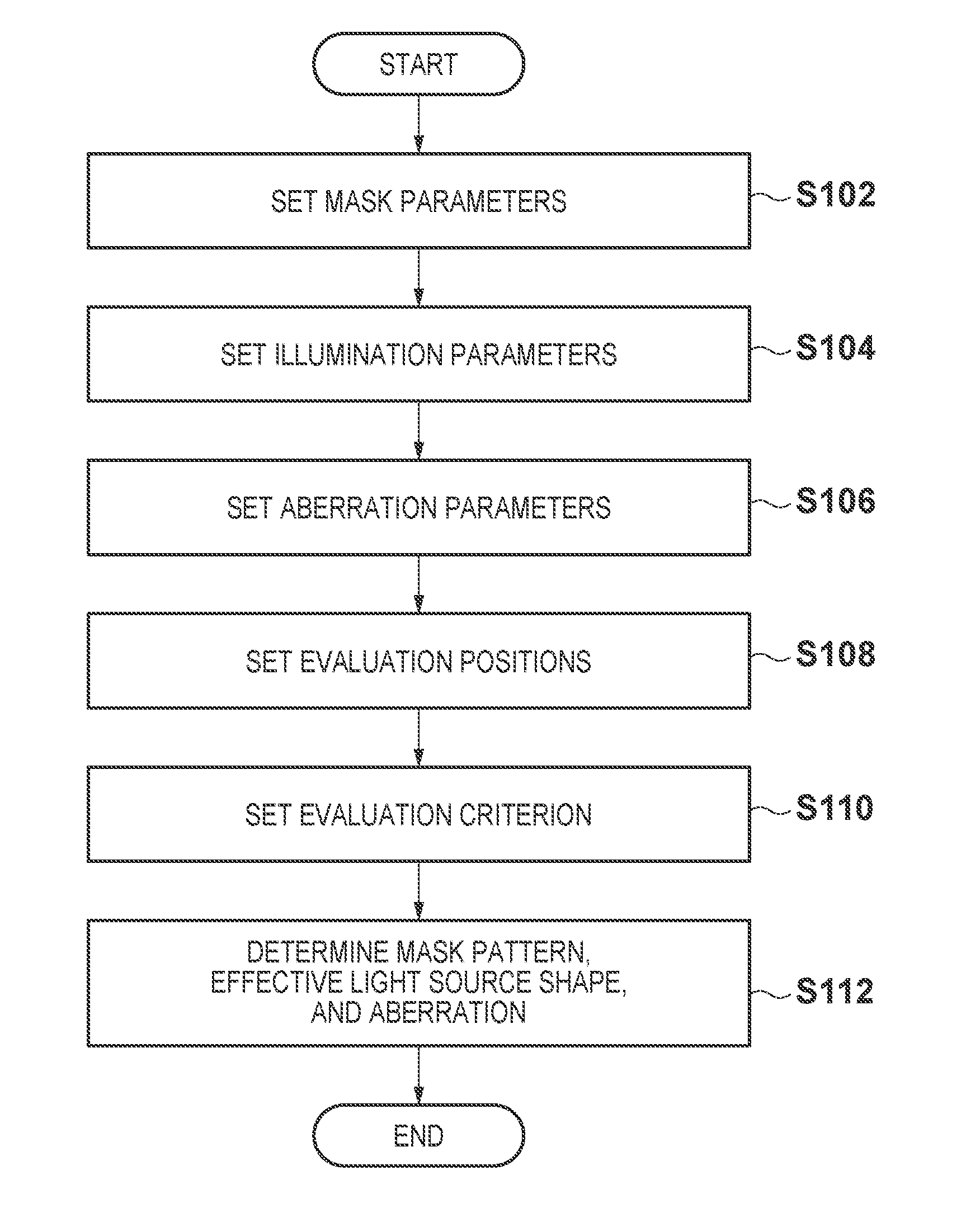
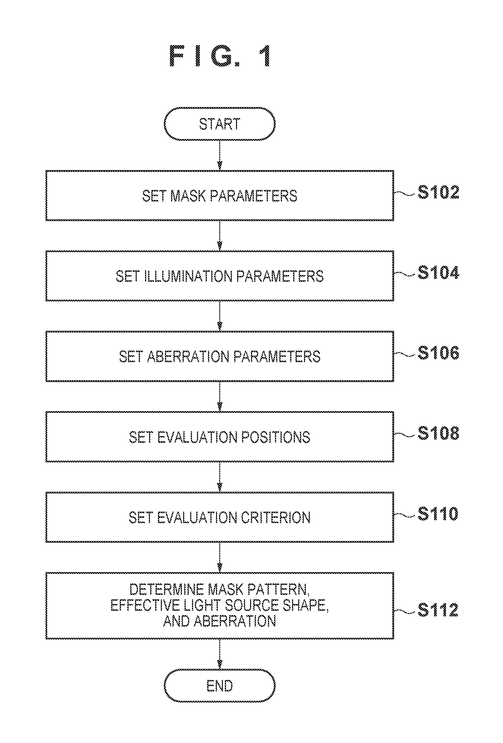
[0031]FIG. 1 is a flowchart for explaining a determination method according to the first embodiment of the present invention. The determination method of this embodiment is executed by an information processing apparatus such as a computer to determine (optimize) the exposure conditions of an exposure apparatus including an illumination optical system which illuminates a mask (reticle), and a projection optical system which projects the pattern of the mask onto a substrate. Note that the exposure conditions can be set in the exposure apparatus, and include, for example, parameters such as the shape, size, and position of the pattern (mask pattern) of the mask, the effective light source shape, and the aberration of the projection optical system.

[0032]In step S102, parameters (mask parameters) are set for the pattern of a mask to be placed on the object plane of the projection optical system.

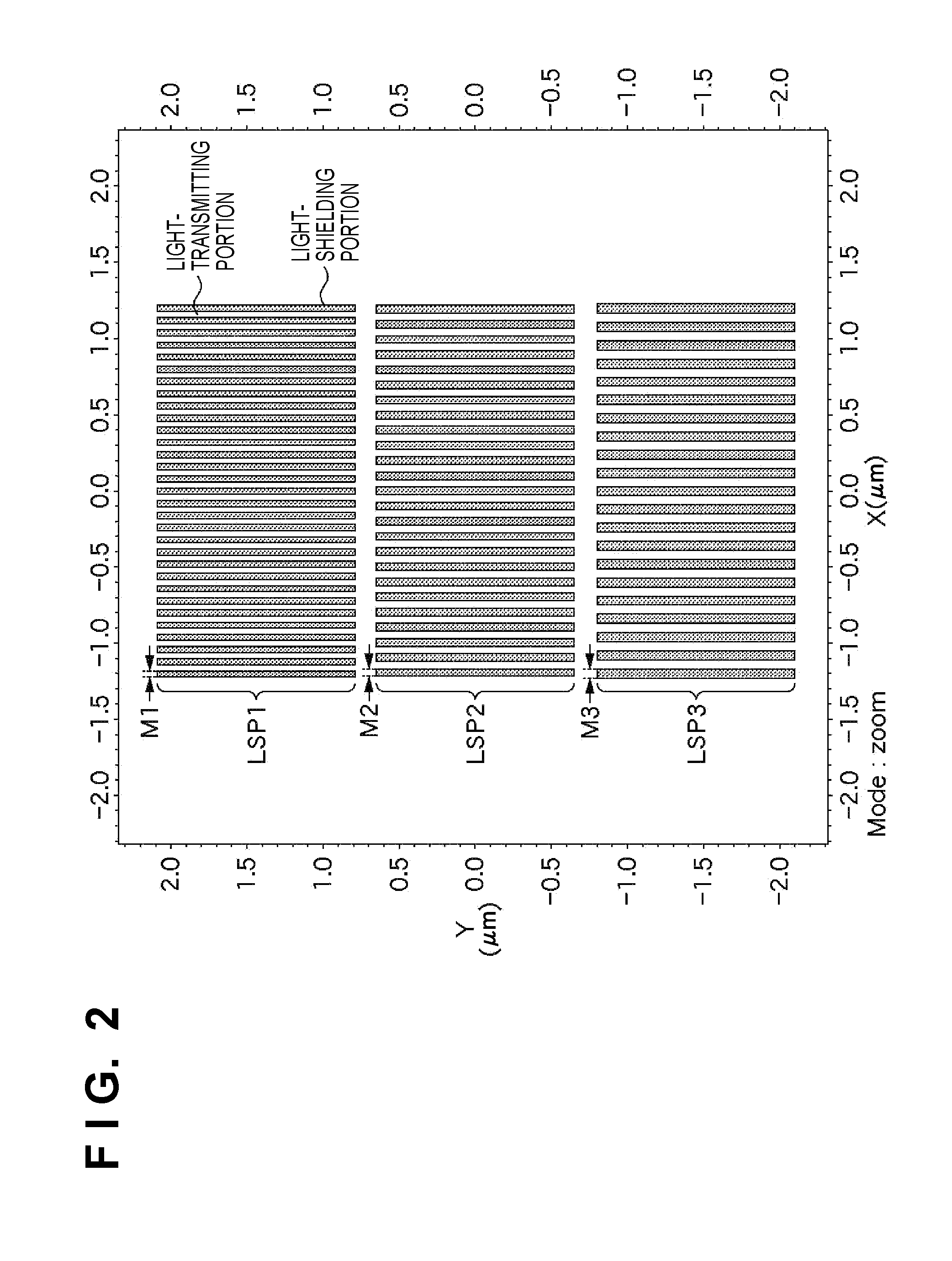
[0033]In this embodiment, mask parameters (also called “mask biases”) M1, M2, and M3 which de...

second embodiment

[0097]In the first embodiment, three types of characteristics: the mask pattern, the effective light source shape, and the aberration of the projection optical system are defined as targets to be optimized. However, the mask pattern can also be excluded from the targets to be optimized. Since a mask used for an exposure apparatus is very expensive, it is desired to avoid remanufacturing a mask (manufacturing it again) after one mask is manufactured. Hence, in this embodiment, the effective light source shape and the aberration of the projection optical system are optimized without changing the mask pattern (that is, fixing the mask pattern).

[0098]FIG. 8 is a flowchart for explaining a determination method according to the second embodiment of the present invention. The determination method in this embodiment is similar to that in the first embodiment, but has step S102A in place of step S102, and step S112A in place of step S112.

[0099]In step S102A, the pattern (mask pattern) of a m...

third embodiment

[0117]FIG. 10 is a flowchart for explaining a determination method according to the third embodiment of the present invention. The determination method of this embodiment determines (optimizes) the exposure conditions of an exposure apparatus including an illumination optical system which illuminates a mask (reticle), and a projection optical system which projects the pattern of the mask onto a substrate, as in the first and second embodiments.

[0118]In step S1002, image heights (evaluation image heights) are set to evaluate optical images of the mask pattern, which are formed on the image plane of the projection optical system. In this embodiment, assuming a step-and-scan exposure apparatus (scanner), five image heights: (−12.6, 0), (−7, 0), (0, 0), (7, 0), and (12.6, 0) are set as evaluation image heights. Note that the coordinate in the slit direction is defined as x, and that in the scan direction is defined as y.

[0119]In step S1004, parameters (mask parameters) are set for the p...


PUM


Abstract

The present invention provides a determination method of determining exposure conditions of an exposure apparatus including an illumination optical system which illuminates a mask, and a projection optical system which projects a pattern of the mask onto a substrate, the method including a step of setting an illumination parameter for a light intensity distribution formed on a pupil plane of the illumination optical system, and an aberration parameter for an aberration of the projection optical system, and a step of determining a value of the illumination parameter and a value of the aberration parameter so that an image performance of an optical image of the pattern of the mask satisfies an evaluation criterion set for a target pattern to be formed on an image plane of the projection optical system.

Description

BACKGROUND OF THE INVENTION[0001]1. Field of the Invention[0002]The present invention relates to a determination method of determining the exposure conditions of an exposure apparatus, a storage medium, and an information processing apparatus.[0003]2. Description of the Related Art[0004]An exposure apparatus which projects and transfers the pattern of a mask (reticle) onto a substrate (for example, a wafer) via a projection optical system is employed to fabricate a semiconductor device using a photolithography technique. In recent years, with miniaturization of semiconductor devices (that is, with a reduction in circuit line width), a demand has arisen for a technique which further improves the resolution of the exposure apparatus.[0005]The exposure apparatus is required to transfer the pattern (its image) of a mask to a desired position on a substrate in a desired shape. However, due to some error factors during exposure, the mask pattern is often transferred to a position deviated...

Claims


Application Information

Patent Timeline
IPC IPC(8): G03B27/72
CPCG03F7/705G03F1/50
Inventor GYODA, YUICHIMIKAMI, KOJITSUJITA, KOUICHIROU
Owner CANON KK
Why Eureka
Try Eureka