
Sub-channelization with power boost

a power boost and sub-channel technology, applied in power management, electrical equipment, wireless commuication services, etc., can solve problems such as worst coverage, and achieve the effect of reducing bandwidth channels and power boosts for uplinks

Active Publication Date: 2013-01-10
MALIKIE INNOVATIONS LTD
View PDF3 Cites 17 Cited by
  • Summary
  • Abstract
  • Description
  • Claims
  • Application Information

AI Technical Summary

Benefits of technology

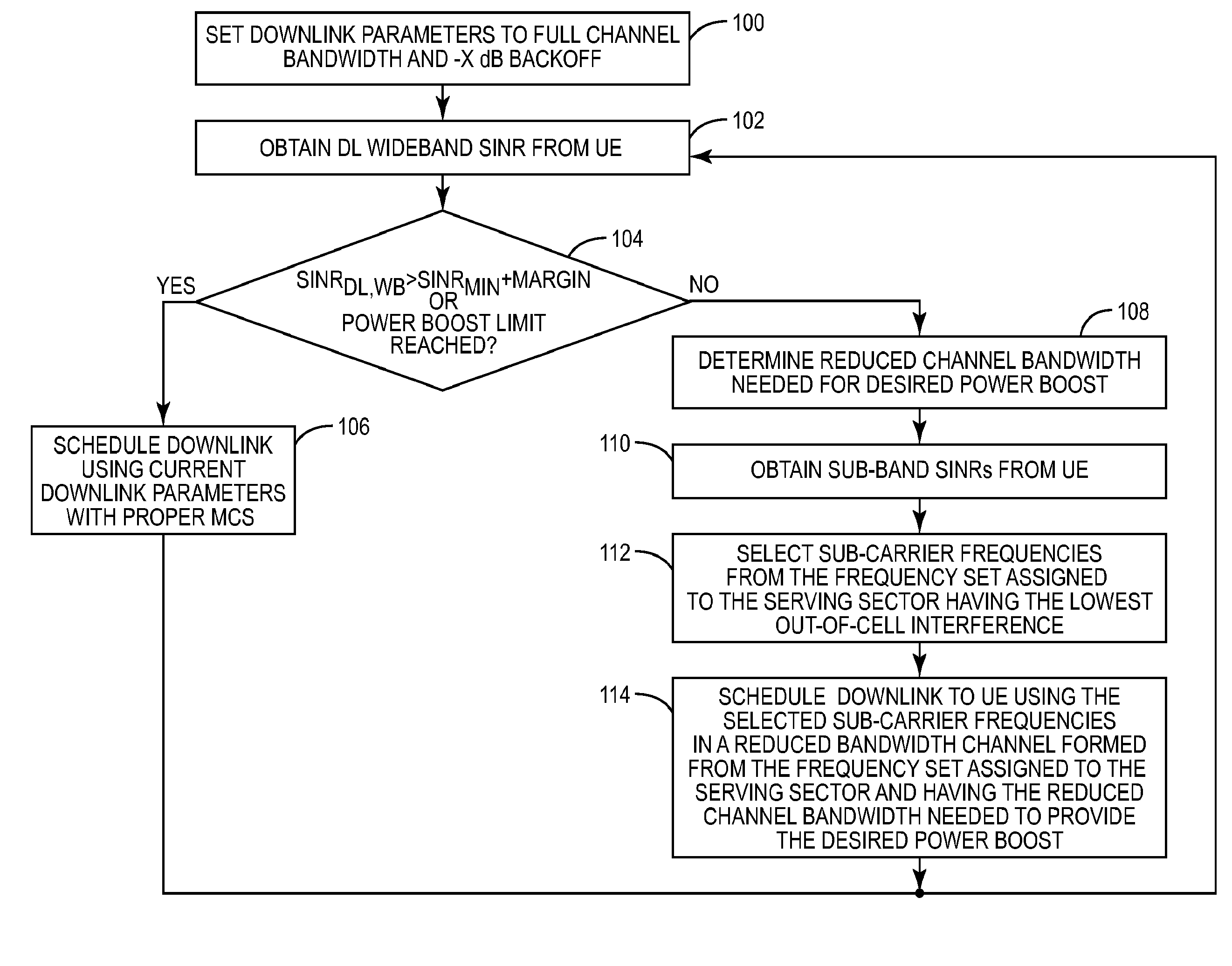
This approach provides a power boost to user devices at cell edges, improving coverage and maintaining high spectrum efficiency by concentrating signal power on a reduced bandwidth channel, thereby increasing SINR and reducing out-of-cell interference.

Problems solved by technology

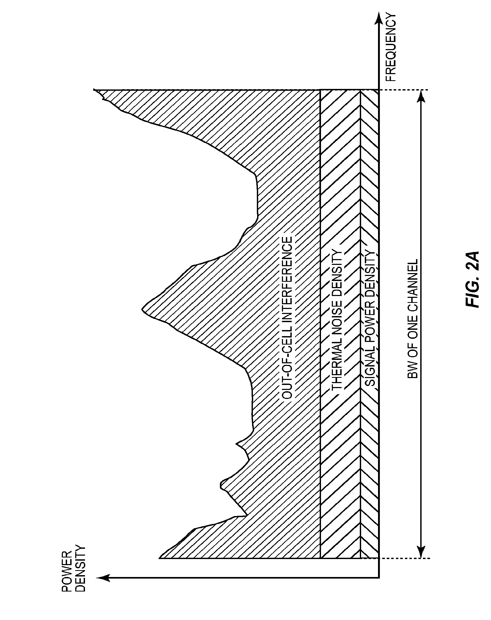
However, when the frequency reuse factor (N) is 1, out-of-cell interference is at its maximum and, therefore, coverage is at its worst.

Method used


Image

  • Sub-channelization with power boost
  • Sub-channelization with power boost
  • Sub-channelization with power boost

Examples


Embodiment Construction

[0019]The embodiments set forth below represent the necessary information to enable those skilled in the art to practice the invention and illustrate the best mode of practicing the invention. Upon reading the following description in light of the accompanying drawing figures, those skilled in the art will understand the concepts of the invention and will recognize applications of these concepts not particularly addressed herein. It should be understood that these concepts and applications fall within the scope of the disclosure and the accompanying claims.

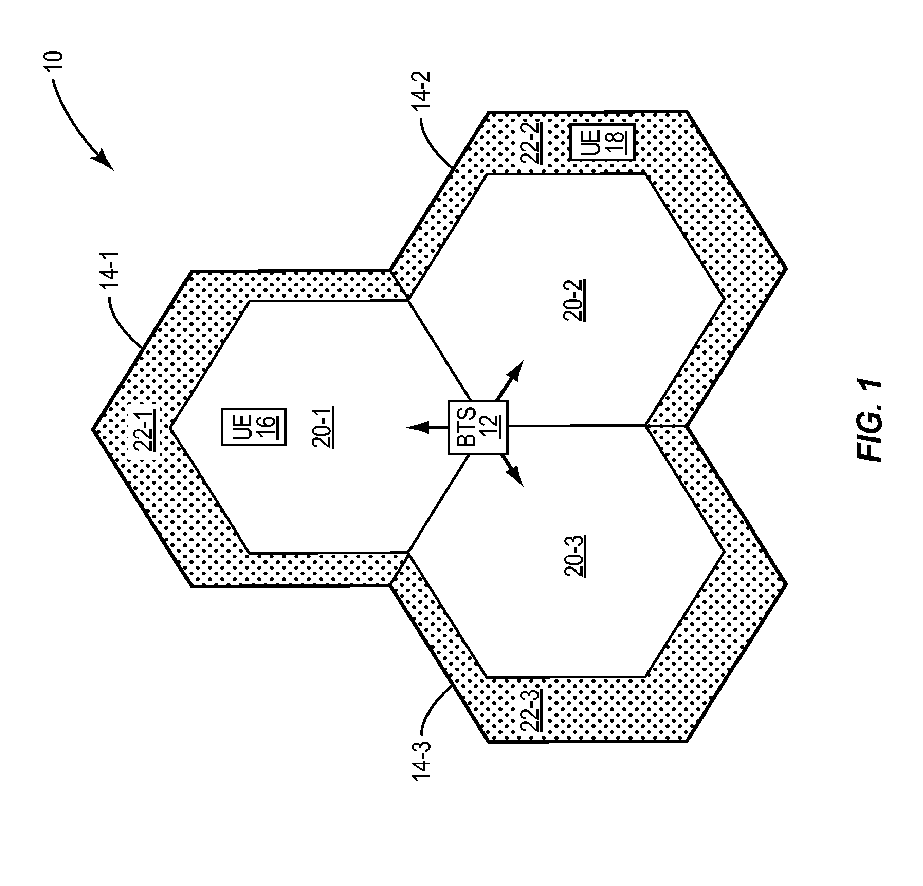
[0020]FIG. 1 illustrates a cell 10 of a cellular communications network according to one embodiment of the present invention. For the discussion herein, the cellular communications network is a Long Term Evolution (LTE) cellular communications network. However, the present invention is not limited thereto. The present invention is applicable to any type of cellular communications network or wireless communications network having a...


PUM


Abstract

A method and system are provided for boosting power for a communications link between a base station and a user device, or user equipment, in a cellular communications network. In one embodiment, the communications link is a downlink between the base station and the user device established via a downlink channel having a full channel bandwidth including a number of sub-carrier frequencies. The base station determines whether a power boost is needed for a downlink to the user device. If so, the base station uses a subset of the sub-carrier frequencies from the full channel bandwidth as a reduced bandwidth channel, or sub-channel, for the downlink to the user device such that signal power is concentrated on the sub-carrier frequencies of the reduced channel bandwidth rather than spread across the sub-carrier frequencies of the full channel bandwidth. As a result, a power boost for the downlink is provided.

Description

[0001]This application claims the benefit of U.S. provisional patent application Ser. Nos. 61 / 188,569 and 61 / 188,609, both of which were filed Aug. 11, 2008 and the disclosures of which are hereby incorporated herein by reference in their entireties.FIELD OF THE INVENTION[0002]The present invention relates to providing a power boost for a wireless communication link.BACKGROUND OF THE INVENTION[0003]In all cellular communications networks, there are opposing requirements for high spectrum efficiency and high area availability, or coverage. As a Fourth Generation (4G) technology, Long Term Evolution (LTE) is expected to provide high spectrum efficiency. Namely, LTE is expected to provide three to four times higher spectrum efficiency than High-Speed Downlink Packet Access (HSDPA) Release 6 for the downlink, and two to three times higher spectrum efficiency than High-Speed Uplink Packet Access (HSUPA) Release 6 for the uplink. In addition, as with any cellular communications network, L...

Claims


Application Information

Patent Timeline
Patent Type & Authority Applications(United States)
IPC IPC(8): H04W52/24H04W72/04
CPCH04W52/241H04W52/346H04W72/0473H04W52/42H04W52/0296H04W52/243H04W72/0453H04W72/232
Inventor CHANG, CHU-RUIFLUET, JACQUES
Owner MALIKIE INNOVATIONS LTD
Learn More