
Reverse Tension Mechanism for a Strapping Machine

a strapping machine and reverse tension technology, applied in the field of strapping machine reverse tension mechanism, can solve the problems of increasing the cost and size of the conventional strapping machine, and achieve the effects of saving horizontal space, compact size, and simple structur

Active Publication Date: 2013-01-17
LAI CHIEN FA
View PDF9 Cites 14 Cited by
  • Summary
  • Abstract
  • Description
  • Claims
  • Application Information

AI Technical Summary

Benefits of technology

The present invention provides a reverse tension mechanism for a strapping machine. This mechanism can retract and tighten a strapping band, and has the benefits of a simple structure, compact size, and improved tightening effect. Its technical effects include improved efficiency and ease of use in strapping materials.

Problems solved by technology

Thus, both the cost and size of the conventional strapping machine are increased.

Method used


Image

  • Reverse Tension Mechanism for a Strapping Machine
  • Reverse Tension Mechanism for a Strapping Machine
  • Reverse Tension Mechanism for a Strapping Machine

Examples


Embodiment Construction

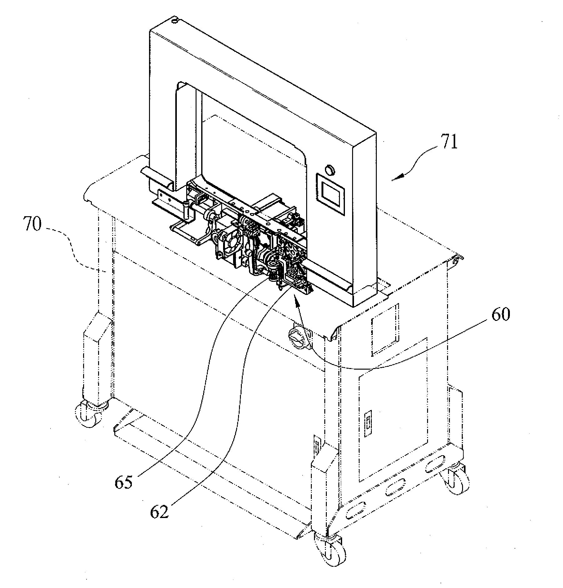
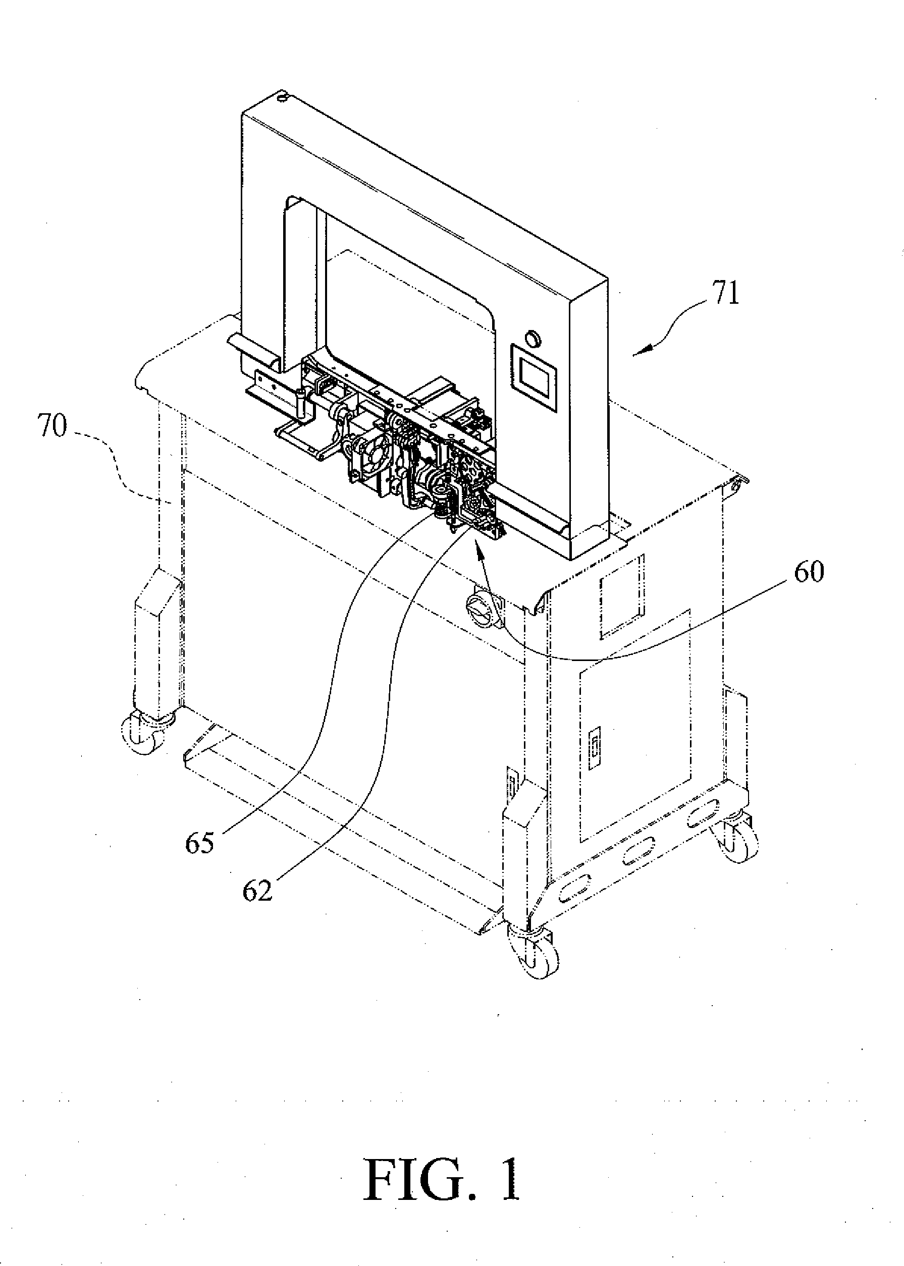
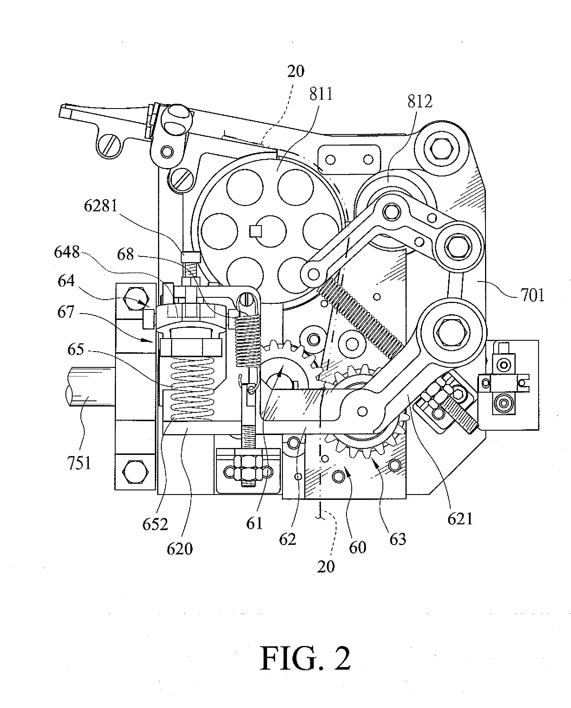
[0022]A reverse tension mechanism for a strapping machine according to the preferred teachings of the present invention is shown in FIGS. 1 through 8 of the drawings and generally designated 60. The reverse tension mechanism 60 is mounted on a machine body 70 of the strapping machine. A guide arch frame 71 is mounted on a top of the machine body 70. A transmission assembly 75, a band feeding assembly 80, a guide wheel unit, a band reel mechanism, and a band storage device are mounted to the machine body 70, wherein the guide wheel unit, the band reel mechanism, and the storage device are conventional. In this embodiment, the transmission assembly 75 includes a camshaft 751 and a cam 72 installed on the camshaft 751 and having a protrusion 721 on an outer periphery of the cam 72 (see FIG. 3). The band feeding assembly 80 includes an active wheel 811, a passive wheel 812, and a motor 81 for driving the active wheel 811. The constructions and actions of the machine body 70, the arch fr...


PUM


Abstract

A reverse tension mechanism for a strapping machine includes an active wheel, a supporting arm installed with a passive wheel, a lever, and a spring. The supporting arm can be moved relative to the active wheel so that a strapping band which passes through between the passive wheel and the active wheel is clamped to control retracting and tightening of the strapping band. A first end of the lever is pivotably connected to a section of the supporting arm, and the spring is vertically installed between a second end of the lever and the section of the supporting arm. The first end of the lever can be activated by a cam to press the spring vertically to produce pushing force to swing the supporting arm.

Description

BACKGROUND OF THE INVENTION[0001]1. Field of the Invention[0002]The present invention relates to a reverse tension mechanism for a strapping machine and, more particularly, to a reverse tension mechanism for retracting and tightening a strapping band for strapping machines.[0003]2. Description of the Related Art[0004]FIGS. 9 to 11 show a conventional strapping machine which includes a forward-reverse assembly 30 and a tension assembly 50. The forward-reverse assembly 30 includes a combination of an active wheel 311 and a passive wheel 312 to perform forwarding and reversing actions of a strapping band 20. The tension assembly 50 includes another combination of an active wheel 511 and a passive wheel 513 to allow the strapping band 20 to extend through therebetween and to be tightened. The tension assembly 50 further includes a lever unit 52 having a horizontal rod 53, a tension arm 54, and a driven arm 55. One end of the horizontal rod 53 is pivotably connected to a machine body 10,...

Claims


Application Information

Patent Timeline
Patent Type & Authority Applications(United States)
IPC IPC(8): B65B13/22
CPCB65B13/22B65B13/06
Inventor LAI
Owner LAI CHIEN FA
Learn More