Hall sensor

a technology of hall sensors and sensors, applied in the field of hall sensors, can solve the problems of unnecessary parallel connection of a plurality of hall sensors, and achieve the effect of simple parallel connection

Active Publication Date: 2013-01-17
TDK MICRONAS GMBH +1
View PDF14 Cites 33 Cited by
  • Summary
  • Abstract
  • Description
  • Claims
  • Application Information

AI Technical Summary

Benefits of technology

[0011]A further advantage is that the contact and interconnect resistances in the series connection of the four Hall elements can be distributed symmetrically ...

Problems solved by technology

A complex parallel connection of a plurality of Hall sensors becomes ...

Method used


Image

  • Hall sensor
  • Hall sensor
  • Hall sensor

Examples


Embodiment Construction

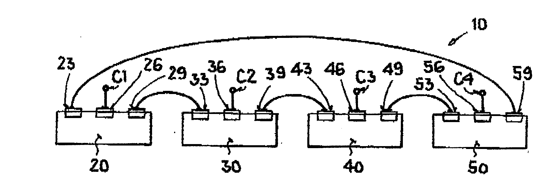
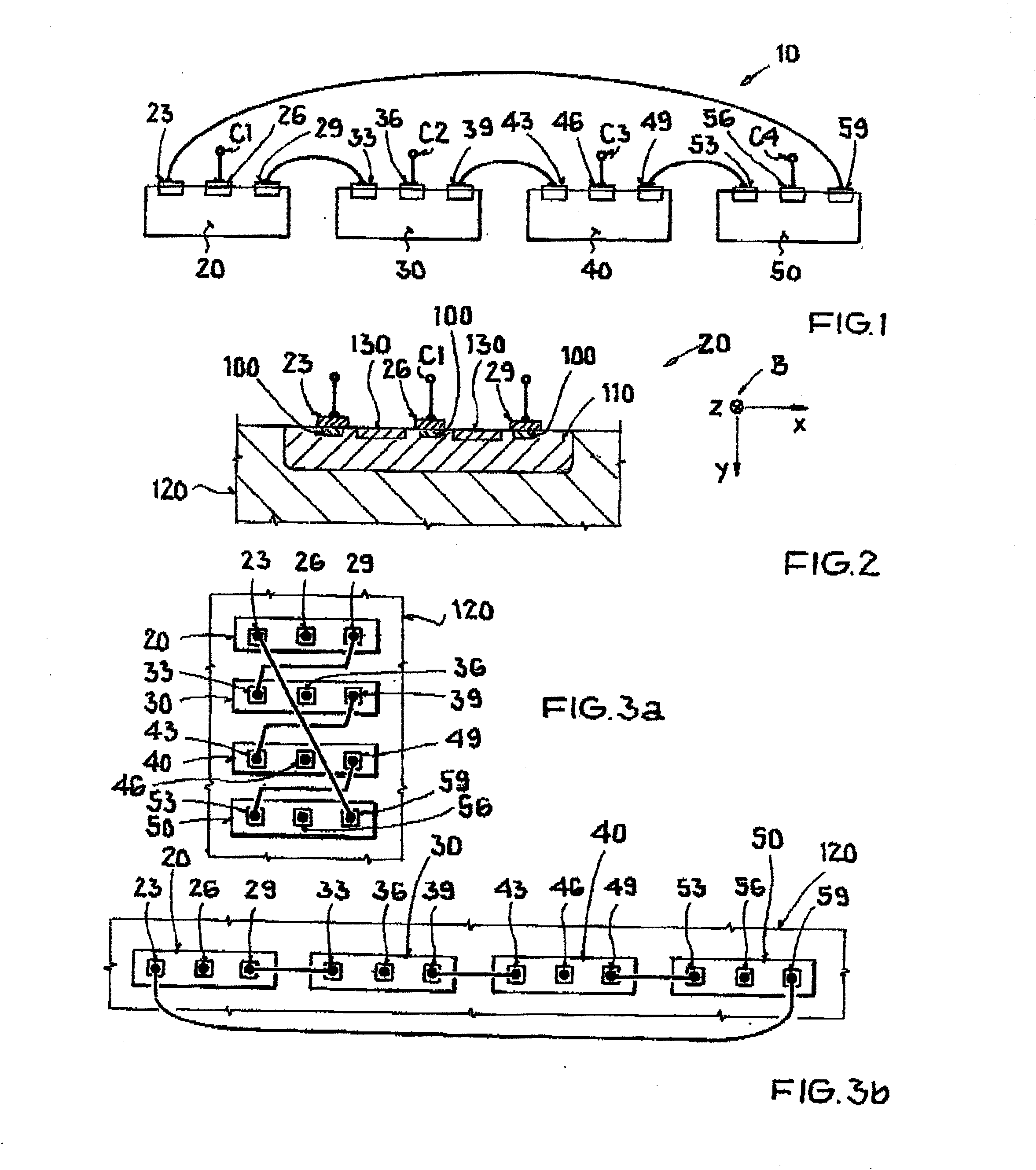
[0023]The illustration in FIG. 1 shows a schematic view of an embodiment of a series connection, according to the invention, of a Hall sensor 10, having a first preferably vertically formed Hall element 20, with a first terminal contact 23, a second terminal contact 26, and a third terminal contact 29, a second preferably vertically formed Hall element 30, with a fourth terminal contact 33, a fifth terminal contact 36, and a sixth terminal contact 39, a third preferably vertically formed Hall element 40, with a seventh terminal contact 43, an eighth terminal contact 46, and a ninth terminal contact 49, and a fourth preferably vertically formed Hall element 50, with a tenth terminal contact 53, an eleventh terminal contact 56, and a twelfth terminal contact 59. Furthermore, first terminal contact 23 is connected to twelfth terminal contact 59. Depending on the mode, according to the arrangement in Table 1, second terminal contact 26 is formed with a first connection point C1 and the ...


PUM


Abstract

A Hall sensor is provided having a first Hall element with a first terminal contact and with a second terminal contact and with a third terminal contact, a second Hall element with a fourth terminal contact and with a fifth terminal contact and with a sixth terminal contact, a third Hall element with a seventh terminal contact and with an eighth terminal contact and with a ninth terminal contact, and a fourth Hall element with a tenth terminal contact and with an eleventh terminal contact and with a twelfth terminal contact. The first Hall element and the second Hall element and the third Hall element and the fourth Hall element are connectable in series.

Description

[0001]This nonprovisional application claims priority to German Patent Application No. DE 10 2011 107 767.0, which was filed in Germany on Jul. 15, 2011, and to U.S. Provisional Application No. 61 / 508,363, which was filed on Jul. 15, 2011, and which are both herein incorporated by reference.BACKGROUND OF THE INVENTION[0002]1. Field of the Invention[0003]The invention relates to a Hall sensor.[0004]2. Description of the Background Art[0005]DE 101 50 955 C1 discloses a Hall sensor. The Hall sensor has a plurality of vertical Hall elements each with five terminal contacts. In this case, up to four Hall elements are designed parallel to one another and the terminal contacts are connected to one another by means of cyclic commutation, to reduce the offset voltage of the Hall sensor in comparison with the offset voltage of a single Hall element. In addition, the offset voltage can be reduced further by means of the so-called “spinning current” method. It is desirable to improve the comple...

Claims


Application Information

Patent Timeline
IPC IPC(8): G01R33/07
CPCG01R33/066G01R33/07G01R33/077
Inventor RAZ, ROIYRUTHER, PATRICKKAUFMANN, TIMOPAUL, OLIVER
Owner TDK MICRONAS GMBH
Why Eureka
Try Eureka