Error amplifier circuit

An error amplifier and amplifier technology, applied in the direction of differential amplifiers, DC-coupled DC amplifiers, etc., can solve the problems of small amplifier output current, slow transient response, and complex compensation network design, and achieve small offset voltage, increase stability, and The effect of improving the response speed and precision

Inactive Publication Date: 2013-11-27
UNIV OF ELECTRONICS SCI & TECH OF CHINA
View PDF6 Cites 10 Cited by
  • Summary
  • Abstract
  • Description
  • Claims
  • Application Information

AI Technical Summary

Problems solved by technology

[0004] The traditional error amplifier is designed as a voltage type, which ensures a high gain of the loop and can obtain sufficient phase margin to stabilize the system, but the output current of the amplifier is small and the transient response is slow, and the design of the compensation network is complicated

Method used


Image

  • Error amplifier circuit
  • Error amplifier circuit
  • Error amplifier circuit

Examples


Embodiment Construction

[0040] Below in conjunction with accompanying drawing, describe technical scheme of the present invention in detail:

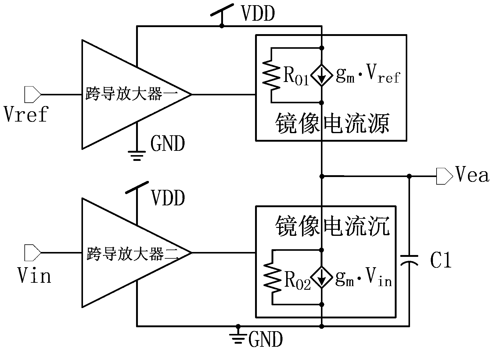
[0041] Such as figure 2 As shown, a kind of error amplifier circuit described in the present invention comprises a first transconductance amplifier, a second transconductance amplifier, a first mirror current, a second mirror current and a first capacitor C1, the first transconductance amplifier The input terminal is the first input terminal Vref of the error amplifier circuit, the output terminal is connected to the first mirror current, the input terminal of the second transconductance amplifier is the second input terminal Vin of the error amplifier circuit, and the output terminal is connected to the second mirror current, The output end of the first mirror current and the output end of the second mirror current are connected to one end of the first capacitor C1 as the output end Vea of ​​the error amplifier circuit, and the other end of the first capacit...


PUM


Abstract

The invention belongs to the technical field of electronics, and relates to an integrated circuit design technology, in particular to a novel current injection/pulling error amplifier circuit. The error amplifier circuit comprises a first transconductance amplifier, a second transconductance amplifier, a first image current source, a second image current source and a first capacitor C1, wherein the input end of the first transconductance amplifier is a first input end Vref of the error amplifier circuit, the output end of the first transconductance amplifier is connected with the first image current source, the input end of the second transconductance amplifier is a second input end Vin of the error amplifier circuit, the output end of the second transconductance amplifier is connected with the second image current source, and the output end of the first image current source and the output end of the second image current source are connected with one end of the first capacitor C1 to serve as an output end Vea of the error amplifier circuit. The error amplifier circuit has the advantages of being capable of adjusting the output voltage, improving the response speed and response accuracy of a system and improving the stability of the system, and is particularly suitable for an error amplifier.

Description

technical field [0001] The invention relates to integrated circuit technology, in particular to a novel current sinking / pulling out error amplifier circuit. Background technique [0002] The error amplifier has always been the core circuit of the converter in the switching power supply, which has an important influence on the fast, accurate and stable operation of the system. [0003] Traditional error amplifiers such as figure 1 As shown, the traditional error amplifier includes bias PMOS transistors M6 and M7, input PMOS transistors M1 and M2, and NMOS transistors M3, M4 and M5; the PMOS transistor M1 is connected to the source of M2 to form a differential pair, and is connected to the M6 ​​transistor. Source, M6 tube provides tail current to the op amp; the gates of PMOS tubes M1 and M2 are respectively used as the positive phase input terminal of the error amplifier V in1 and inverting input V in2 The gates of the NMOS transistors M3 and M4 are connected to form a cur...

Claims


Application Information

Patent Timeline
Patent Type & Authority Applications(China)
IPC IPC(8): H03F3/45
Inventor 方健谷洪波潘华彭宜建赵前利李源
Owner UNIV OF ELECTRONICS SCI & TECH OF CHINA
Why Eureka
Try Eureka