Weak signal reading circuit

A weak signal and readout circuit technology, applied in the direction of logic circuit interface device, logic circuit connection/interface layout, etc., can solve the large offset voltage of the operational amplifier, which affects weak signal detection and readout, and cannot be filtered by the low frequency filter 400 And other issues

Active Publication Date: 2016-08-24
SOI MICRO CO LTD
View PDF4 Cites 9 Cited by
  • Summary
  • Abstract
  • Description
  • Claims
  • Application Information

AI Technical Summary

Problems solved by technology

Since the switching device in the first chopper 100 is turned on, there will be channel charge in the channel of the switching device, and the moment the switching device is turned on or off, the channel charge flows into or out of the switching device, that is, the charge of the switching device Injection effect, will introduce error, cause chopper ripple, make operational amplifier 200 output larger offset voltage
Moreover, since the difference between the frequency of the offset voltage and the frequency of the weak signal is very small, it cannot be filtered by the low-frequency filter 400, forming a residual offset, such as figure 2 as shown in (d)
At this time, the signal processed by the existing weak signal readout circuit has a low signal-to-noise ratio, which affects the detection and readout of weak signals, and the accuracy of the signal processing system is poor.

Method used


Image

  • Weak signal reading circuit
  • Weak signal reading circuit
  • Weak signal reading circuit

Examples


Embodiment 1

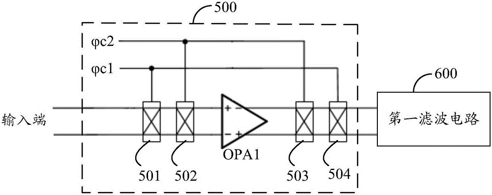
[0090] see image 3 , which is a schematic diagram of Embodiment 1 of the weak signal readout circuit provided by the present invention.

[0091] The weak signal readout circuit provided in this embodiment includes: a chopper amplifier circuit 500;

[0092] The chopper amplifier circuit 500 includes: a first chopper 501, a second chopper 502, a third chopper 503, a fourth chopper 504 and a first operational amplifier OPA1;

[0093] The input terminal of the first chopper 501 is connected to a weak signal, the positive pole of the output terminal of the first chopper 501 is connected to the positive pole of the input terminal of the second chopper 502, and the positive pole of the input terminal of the first chopper 501 The negative pole of the output terminal is connected to the negative pole of the input terminal of the second chopper 502;

[0094] The positive pole of the output terminal of the second chopper 502 is connected to the positive input terminal of the first ope...

Embodiment 2

[0111] see Figure 4 , which is a schematic diagram of Embodiment 2 of the weak signal readout circuit provided by the present invention. Compared to image 3 , this embodiment provides a more specific schematic diagram of a weak signal readout circuit.

[0112] The chopping amplifier circuit 500 further includes: a second operational amplifier OPA2, a third operational amplifier OPA3, a first resistor R1, a second resistor R2, a first capacitor C1, a second capacitor C2, and a third capacitor C3;

[0113] The chopping amplifier circuit 500 adopts a negative feedback structure to ensure the gain accuracy of the chopping amplifier circuit.

[0114] The positive phase input terminal of the second operational amplifier OPA2 is connected to the negative pole of the output terminal of the fourth chopper 504, and the inverting input terminal of the second operational amplifier OPA2 is connected to the negative pole of the output terminal of the fourth chopper 504. positive pole, ...

Embodiment 3

[0171] see Figure 6 , which is a schematic diagram of Embodiment 3 of the weak signal readout circuit provided by the present invention.

[0172] The weak signal readout circuit provided in this embodiment further includes: a first filter circuit 600;

[0173] The first filter circuit 600 is used to filter out harmonic components whose frequency is greater than a first preset frequency in the output signal of the chopper amplifier circuit 500;

[0174] The first preset frequency is greater than the frequency of the weak signal.

[0175] The first filter circuit 600 can filter out noise and offset voltage in the output signal of the chopper amplifier circuit 500 .

[0176] It can be understood that there are many filter circuit topologies with various structures, all of which can perform the above-mentioned filtering function. The topological structure of one of the filter circuits will be introduced below, and the other circuit topological structures will not be repeated h...


PUM


Abstract

The embodiment of the invention discloses a weak signal reading circuit comprising a chopper amplifying circuit. The chopper amplifying circuit comprises a first chopper, a second chopper, a third chopper, a fourth chopper, and a first operational amplifier. The input end of the first chopper is connected with a weak signal. The output end of the first chopper is connected with the input end of the first operational amplifier via the second chopper. The output end of the first operational amplifier is connected with the input end of the fourth chopper via the third chopper. The output end of the fourth chopper is connected with a first filter circuit. The first chopper and the fourth chopper are controlled by a first chopping signal. The second chopper and the third chopper are controlled by a second chopping signal. The frequency of the first chopping signal is lower than that of the second chopping signal. The weak signal reading circuit may decrease offset voltage due to chopping ripples, reduces influence of noise and the offset voltage on the reading of the weak signal, increases the signal-to-noise ratio of a signal and the precision of a signal processing system.

Description

technical field [0001] The invention relates to the technical field of integrated circuits, in particular to a weak signal readout circuit. Background technique [0002] In today's era of advanced technology, sensors are widely used in industrial control, medical treatment, agriculture, and national defense and military fields. With the rapid development of integrated circuit technology, an important development trend of sensor technology is to realize the monolithic integration of sensors and their readout circuits. Due to the small amplitude and low frequency of the weak signal output by the sensor, it is easily affected by non-ideal factors such as environmental noise and offset voltage. Therefore, it is necessary to use a high-performance readout circuit to process the weak signal output by the sensor, amplify the weak signal into a signal that is easy to measure, and remove the influence of non-ideal factors such as environmental noise and offset voltage, and improve t...

Claims


Application Information

Patent Timeline
Patent Type & Authority Applications(China)
IPC IPC(8): H03K19/0175
CPCH03K19/017509
Inventor 何青王玮冰李佳侯影孙业超
Owner SOI MICRO CO LTD
Why Eureka
Try Eureka