
Lock device for power supplying plug

a technology of locking device and power supply plug, which is applied in the direction of gas pressure propulsion mounting, coupling device connection, programme control, etc., can solve the problems of power supply plug theft, power supply plug removal, and battery charging time that is longer,

Inactive Publication Date: 2013-01-17
KK TOKAI RIKA DENKI SEISAKUSHO
View PDF7 Cites 42 Cited by
  • Summary
  • Abstract
  • Description
  • Claims
  • Application Information

AI Technical Summary

Benefits of technology

The patent is about a lock device for power supply plugs that uses a smart system to improve security. The lock device includes an antenna that transmits a wireless signal in the LF band near the inlet. When the wireless signal triggers communication between the vehicle and the electronic key, the lock allows for the removal of the power supplying plug. This prevents unauthorized removal of the plug.

Problems solved by technology

The charging of a battery requires a longer time compared to filling a gasoline vehicle with gasoline.
Thus, the user will leave the vehicle with the power supplying plug connected to the inlet for a long period.
As a result, for example, someone may remove the power supplying plug from the vehicle that is being supplied with power in an unauthorized manner to connect the power supplying plug to another vehicle and steal electricity.
The power supplying plug may also be stolen.
When the lock bar is in such a lock state, the power supplying plug cannot be removed from the inlet.
Superimposed LF band wireless signals interfere with and cancel each other.
When such interference occurs, even when the electronic key enters an area in which the LF band wireless signal can be received, the electronic key may not be able to receive the wireless signal.
In such a case, the lock device for the power supplying plug does not permit removal of the power supplying plug.

Method used


Image

  • Lock device for power supplying plug
  • Lock device for power supplying plug
  • Lock device for power supplying plug

Examples


Embodiment Construction

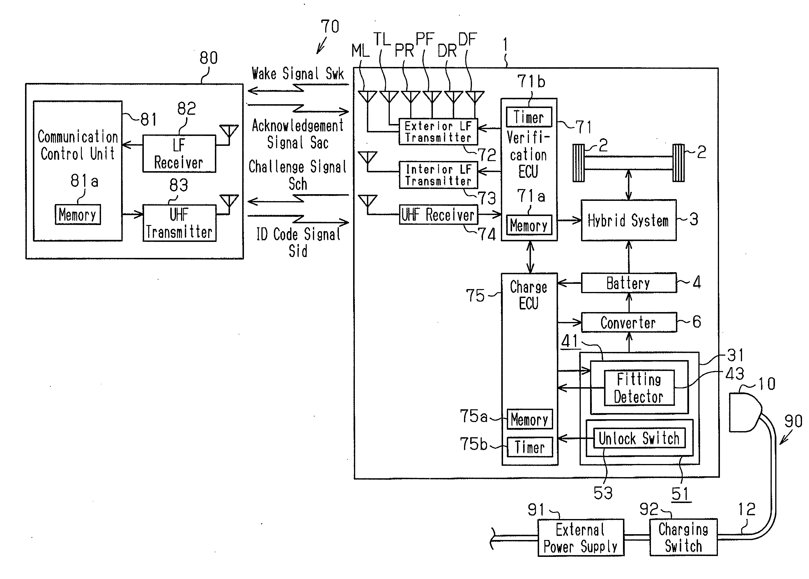
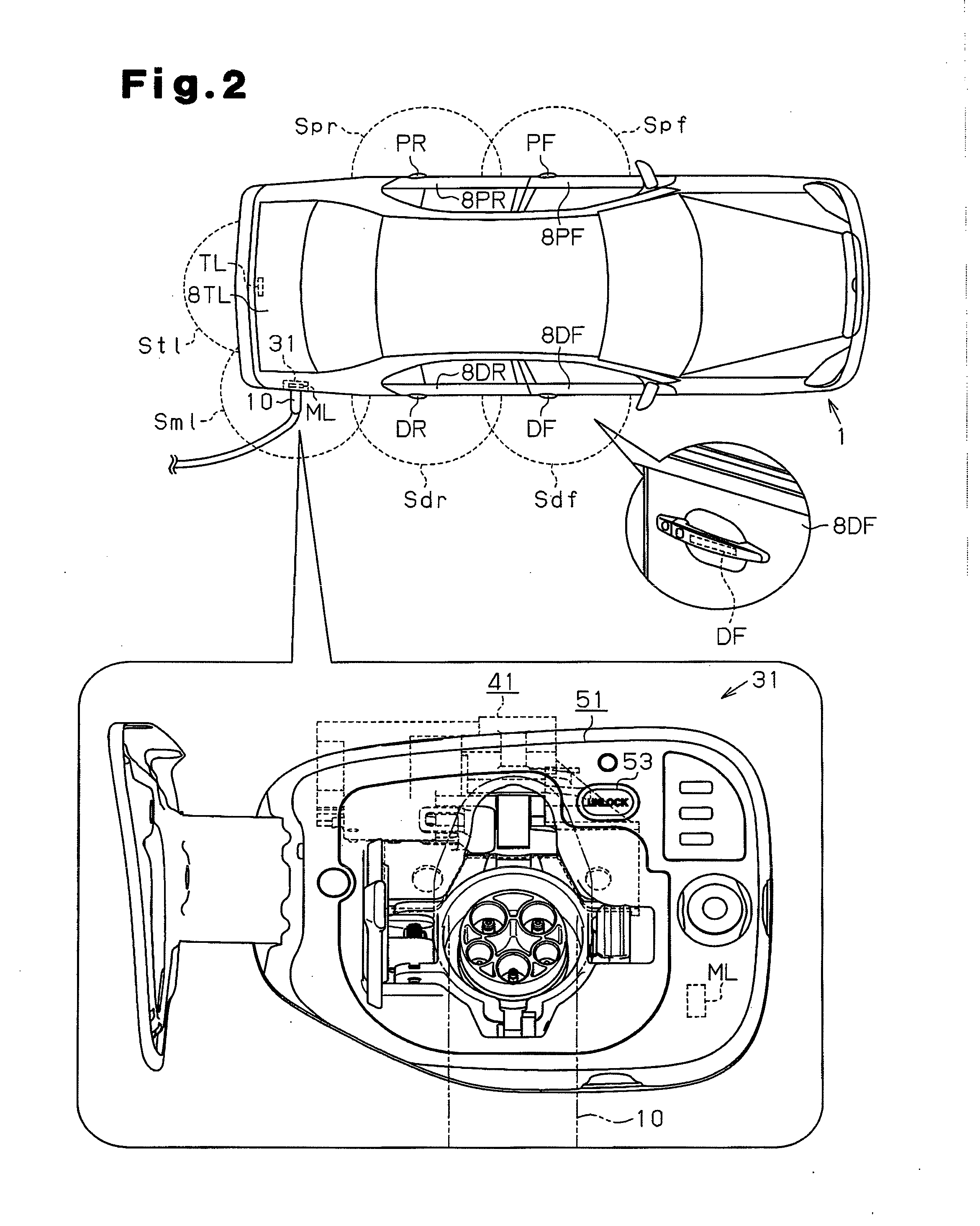
[0015]A lock device for a power supplying plug according to one embodiment of the present invention will now be described with reference to the drawings. The lock device is applied to a plug-in hybrid vehicle.

[0016]Electronic Key System

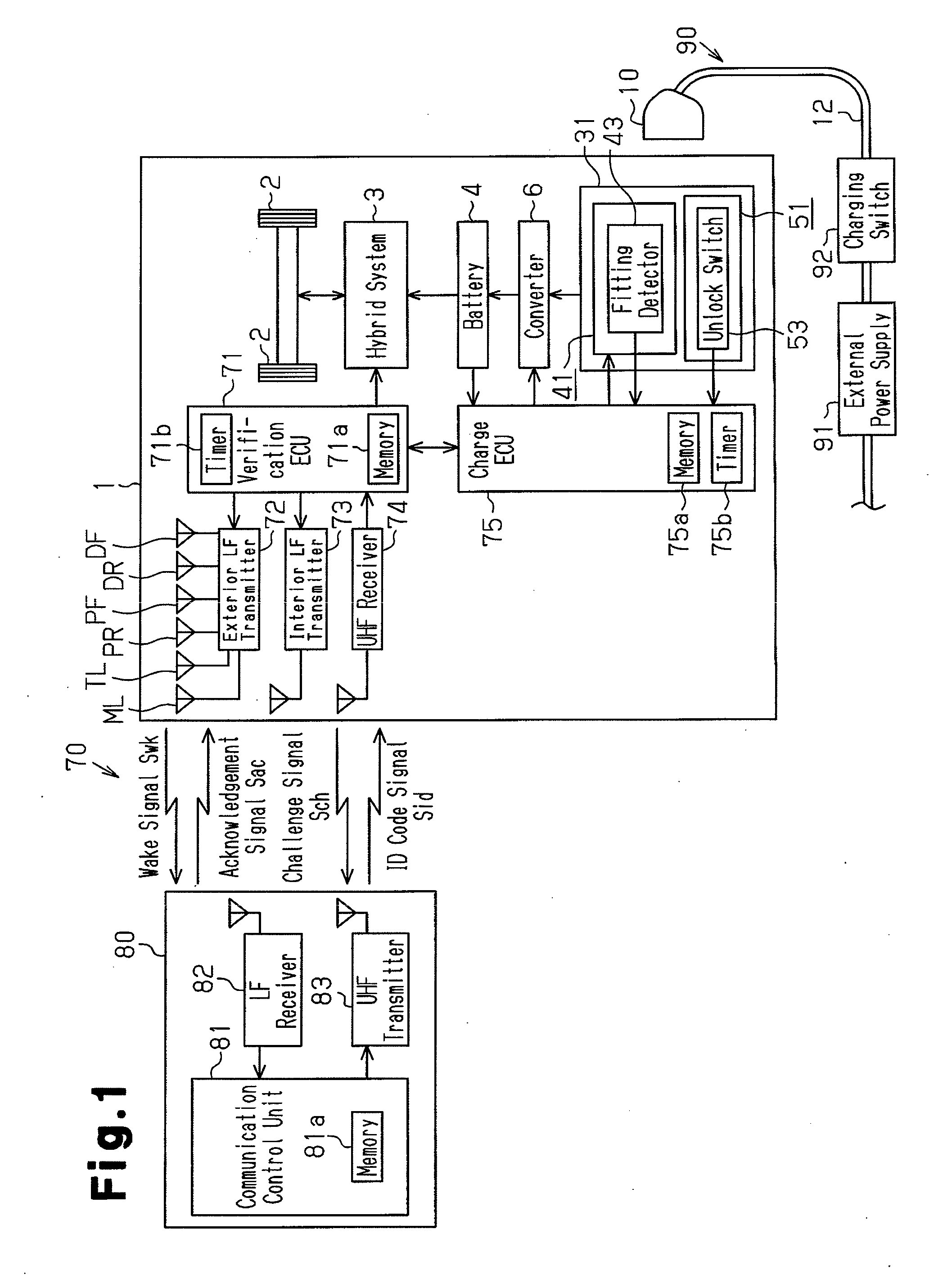
[0017]Referring to FIG. 1, a vehicle 1 includes an electronic key system 70 that permits, for example, the locking and unlocking of the vehicle doors without the need for the driver to actually use a vehicle key. The electronic key system 70 includes an electronic key 80 that performs communication with the vehicle 1.

[0018]The vehicle 1 includes an electronic control unit (ECU) 71 that verifies ID codes of the electronic key 80 and the vehicle 1. Further, the vehicle 1 includes an exterior low frequency (LF) transmitter 72, an interior LF transmitter 73, and an ultra high frequency (UHF) receiver 74. The verification ECU 71 includes a memory 71a, which stores an ID code that is a key code unique to the vehicle 1. The exterior LF transmitter 72, the in...


PUM


Abstract

A lock device for a power supplying plug arranged in a vehicle that performs wireless communication with an electronic key. The lock device includes a charge ECU that restricts unauthorized removal of the power supplying plug from an inlet of the vehicle. The vehicle includes antennas that transmit a wireless signal. A first one of the antennas relates to permission for removal of the power supplying plug. A second one of the antennas relates to unlocking or permission for unlocking of a door. A charge ECU stops transmitting the wireless signal from the first antenna when the vehicle is parked and the second antenna transmits the wireless signal. The charge ECU stops the transmission of the wireless signal related to the unlocking of the door when the wireless signal related to removal of the power supplying plug is transmitted.

Description

CROSS-REFERENCE TO RELATED APPLICATIONS[0001]This application is based upon and claims the benefit of priority from prior Japanese Patent Application No. 2011-154135, filed on Jul. 12, 2011, the entire contents of which are incorporated herein by reference.BACKGROUND OF THE INVENTION[0002]The present invention relates to a lock device for a power supplying plug connected to a power receiving connector to charge a battery.[0003]Automobile manufacturers are developing electric vehicles (including hybrid vehicles) that use motors as drive sources to lower exhaust gas emissions. In such an electric vehicle, a battery drives the drive source. When the state of charge of the battery becomes low, the battery must be charged using a power supply provided in a household or a charging station. Thus, an electric vehicle includes a charging system that can easily be used by a user. Japanese Laid-Open Patent Publication No. 9-161898 describes such a system. In this system, an inlet (power receiv...

Claims


Application Information

Patent Timeline
IPC IPC(8): G05B19/00B60K6/20B60L50/16E05B49/00E05B83/00H01R13/62H02J7/00
CPCH01R13/6397Y04S30/14B60L11/14B60L11/1846B60L2210/30B60L2240/80B60L2250/16B60L2270/32B60L2270/34Y02T10/7077Y02T10/7005Y02T10/7241Y02T90/16Y02T90/163Y02T90/169Y02T10/70Y02T90/121Y02T90/14Y02T90/128Y02T90/127B60L11/1818Y02T10/7072B60L53/16B60L50/16B60L53/65Y02T10/72Y02T90/12Y02T90/167
Inventor KURAMOCHI, YUICHIKATAGIRI, TOSHIHARUKAHARA, KEIJIKURUMIZAWA, NAOTOHIRASHITA, TAKAHIRO
Owner KK TOKAI RIKA DENKI SEISAKUSHO
Learn More