Spectral color sensor and image forming apparatus

Inactive Publication Date: 2013-01-17
CANON KK
View PDF5 Cites 17 Cited by
  • Summary
  • Abstract
  • Description
  • Claims
  • Application Information

AI Technical Summary

Benefits of technology

[0015]According to the present invention, it is possible to provide a spectral color sensor capable of updating stray light components and taking col

Problems solved by technology

However, it is known that a high color measurement accuracy cannot be obtained if the relationship between the pixels in the area sensor and the wavelength of the reflected light is not precise.
In addition to dark outputs from light-receiving elements, stray light components that cannot be completely removed are present in noise.
If these stray light components are not taken into consideration, they become noise components in the original signal, and cause a drop in the color measurement accuracy.
Note that stray light is light resulting from some of the light source leaking within the sensor unit and that reaches the light-receivi

Method used


Image

  • Spectral color sensor and image forming apparatus
  • Spectral color sensor and image forming apparatus
  • Spectral color sensor and image forming apparatus

Examples


first embodiment

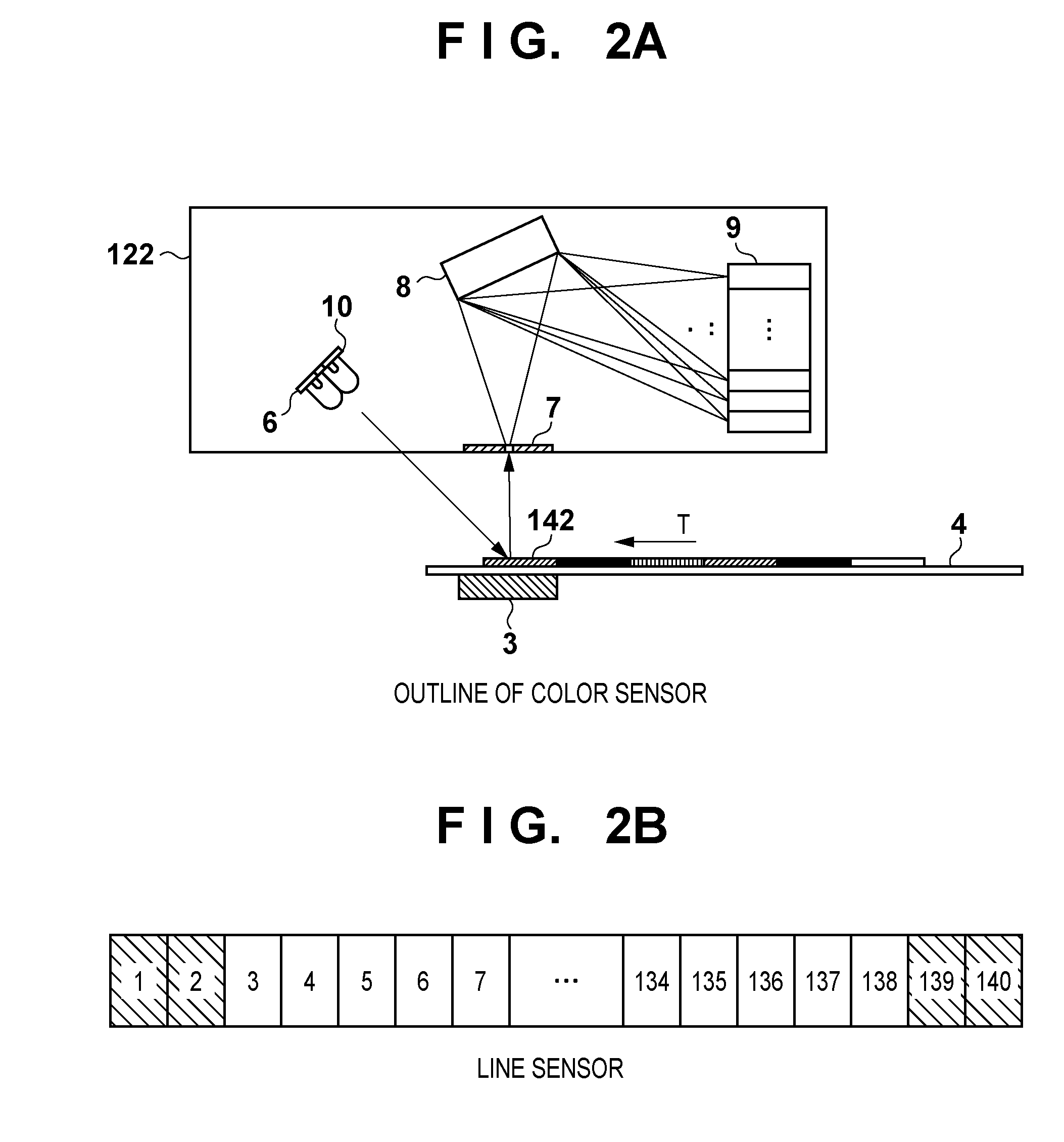
[0028]First, a first embodiment of the present invention will be described. In the first embodiment, a relationship between the detection wavelength properties of a color sensor and the positions of the pixels in the color sensor is measured, and pre-prepared stray light wavelength properties are corrected based on a result of the measurement. Furthermore, a method used in correcting an output when the color sensor measures post-wavelength correction stray light components will be described as well. Hereinafter, the configuration of a printer, an outline of a spectral color sensor, and a stray light correction method will be described in that order.

[0029]Printer Configuration

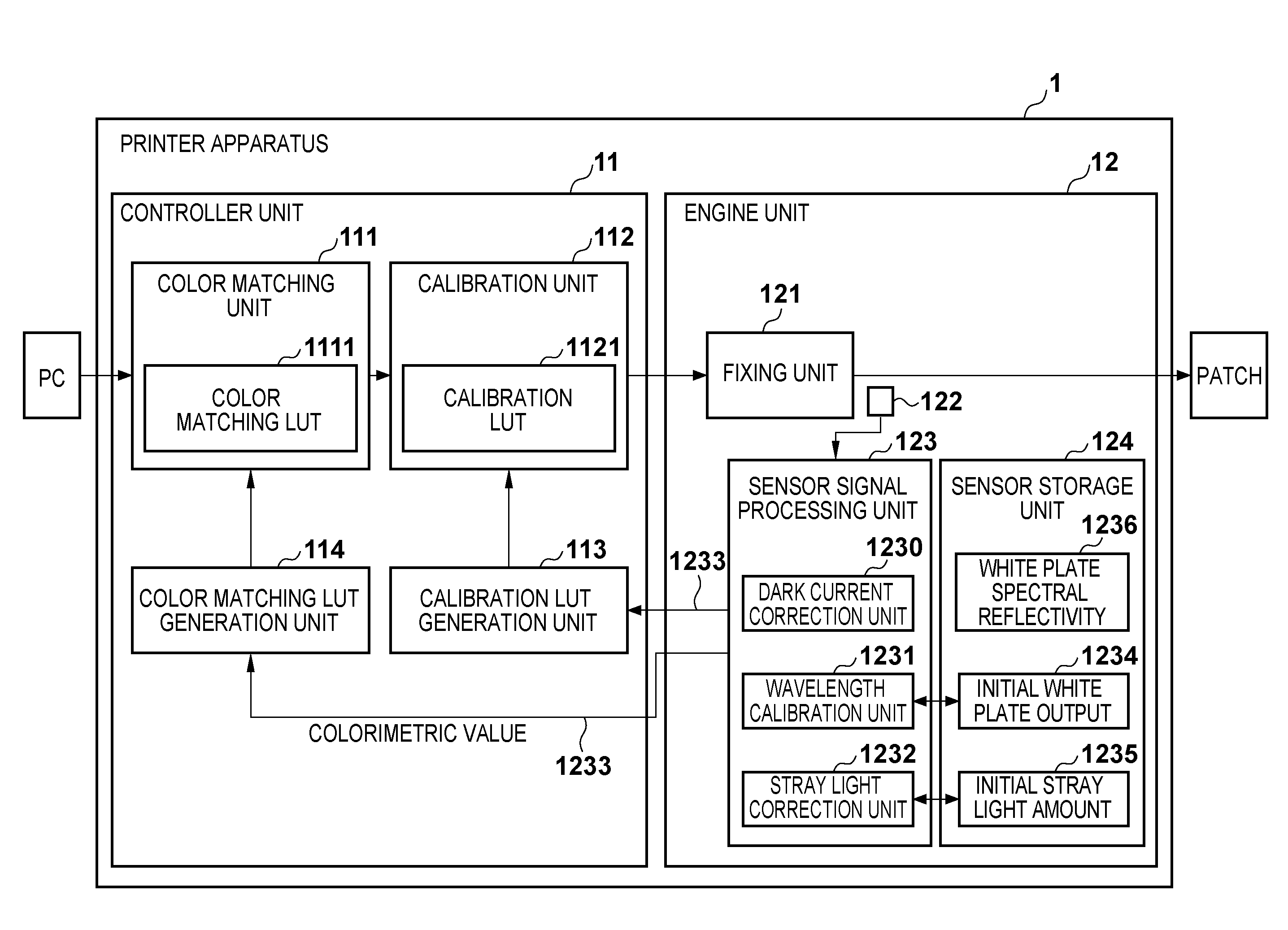
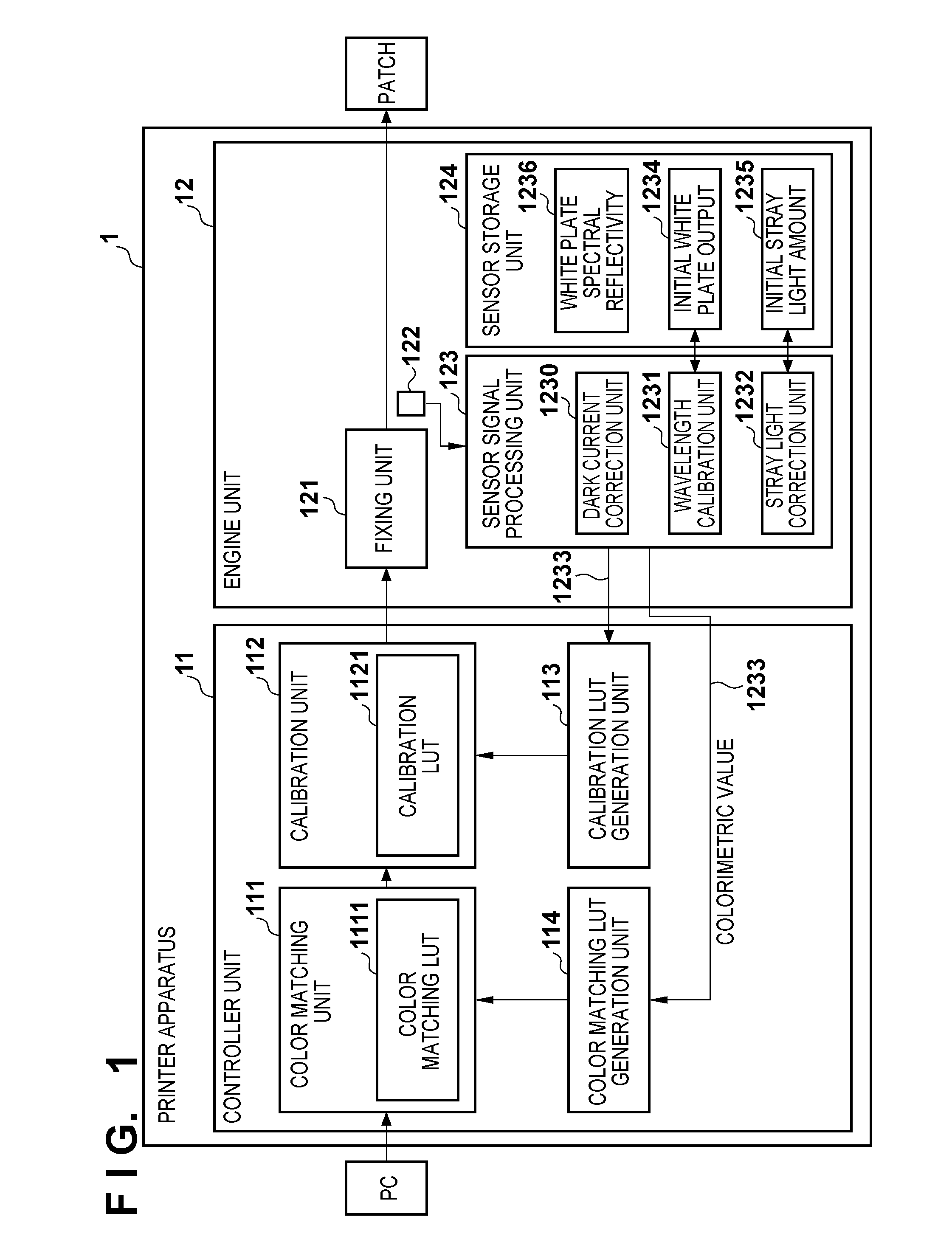
[0030]FIG. 1 is a block diagram illustrating an example of the configuration of a printer apparatus, serving as an image forming apparatus according to the present embodiment. Note that a printer apparatus 1 shown here may also be a multi-function peripheral (MFP) that has a printing function. The functional blo...

second embodiment

[0069]Next, a second embodiment of the present invention will be described. The first embodiment describes an example in which an accurate signal is obtained by estimating changes in the wavelength direction of stray light based on the output of the spectral color sensor 122 provided in the printer apparatus 1. As opposed to this, the present embodiment describes an example in which an even more accurate signal is obtained by estimating changes in the intensity direction, or in other words, in the stray light amount itself, in addition to changes in the wavelength direction. Accordingly, the present embodiment and the first embodiment differ primarily in that in the stray light amount correction, the intensity direction is corrected in addition to the wavelength direction. Accordingly, in the present embodiment, the color measurement flow and the like are the same as in the first embodiment; elements that are the same will be given the same reference numerals as shown in FIG. 1 thro...


PUM


Abstract

A spectral color sensor including a spectroscopic unit that disperses reflected light from a measurement target, and a light detection element that detects the dispersed light from the reflected light, comprises: a storage unit that stores a correspondence relationship between a pre-measured wavelength of the dispersed light projected on the light detection element and a projection position, as well as a stray light component; a first correction unit that, based on a measurement result when a color is measured, corrects the correspondence relationship between the wavelength of the dispersed light projected on the light detection element and the projection position stored in the storage unit; and a second correction unit that carry out wavelength correction on the stray light component stored in the storage unit using the corrected correspondence relationship between the wavelength and the projection position.

Description

BACKGROUND OF THE INVENTION[0001]1. Field of the Invention[0002]The present invention relates to spectral color sensors and image forming apparatuses such as printers and photocopiers, and particularly relates to the removal of stray light components in a spectral color sensor.[0003]2. Description of the Related Art[0004]Conventionally, color conversion lookup tables (abbreviated as “LUT” hereinafter) are used in printing apparatuses such as printers in order to output desired colors. Color conversion LUTs include LUTs used in calibration for keeping the printer in a certain stable state, LUTs used in color matching such as ICC profiles, and so on.[0005]Some models of printers include a spectral color sensor within the printer engine. This type of printer prints a color index (called a “patch” hereinafter) such as IT8 7 / 3 (ISO 12642 output target) prior to or during the execution of a print job, and measures the patch using the included spectral color sensor. The color measurement r...

Claims


Application Information

Patent Timeline
IPC IPC(8): G01J3/46
CPCG01J3/501G01J3/524G01J3/502
Inventor KITA, HIROSHIEBIHARA, SHUN-ICHI
Owner CANON KK
Why Eureka
Try Eureka