Method for controlling a frequency converter and frequency converter

a frequency converter and control method technology, applied in the direction of ac-ac conversion, power conversion systems, circuit arrangements, etc., can solve the problems of inability to realize transient over load and over speed of wind turbines, inability to control the operation speed and power of generators, and increase the unnecessary losses of fixed dc link voltage at the converter and the generator, etc., to achieve the effect of short signal transmission, enhanced control reliability, and easy implementation

Inactive Publication Date: 2013-01-17
SIEMENS AG
View PDF14 Cites 20 Cited by
  • Summary
  • Abstract
  • Description
  • Claims
  • Application Information

AI Technical Summary

Benefits of technology

[0024]The DC link voltage controller may be arranged in the rectifier controller and / or in the inverter controller. It can be chosen if the DC link voltage is controlled from the generator side, the grid side or from both sides. Locating the DC link voltage controller inside these controllers has the benefit of short signal transmission and easy implementation. Of course, it can be located in another controller like for example a wind turbine controller.
[0025]The DC voltage controller may comprise an input for a power of the AC input power, for a torque of the generator, for an angular velocity of the generator and / or for a power of the AC output power. These further inputs can enhance reliability of control.

Problems solved by technology

In this case, the fixed DC link voltage increases unnecessary losses at the converter and the generator.
Therefore, transient over load and over speed of the wind turbine cannot be realised due to the limited fixed DC link voltage.
The operating speed and power of the generator can be limited by the fixed DC link voltage as well.

Method used


Image

  • Method for controlling a frequency converter and frequency converter
  • Method for controlling a frequency converter and frequency converter
  • Method for controlling a frequency converter and frequency converter

Examples


Embodiment Construction

[0035]In the following detailed description, reference is made to the accompanying drawings which form a part hereof and in which are shown by way of illustration specific embodiments. In this regard, directional terminology, such as “top” or “bottom” etc. is used with reference to the orientation of the figure(s) being described. Because components of embodiments can be positioned in a number of different orientations, the directional terminology is used for purposes of illustration and is in no way limiting.

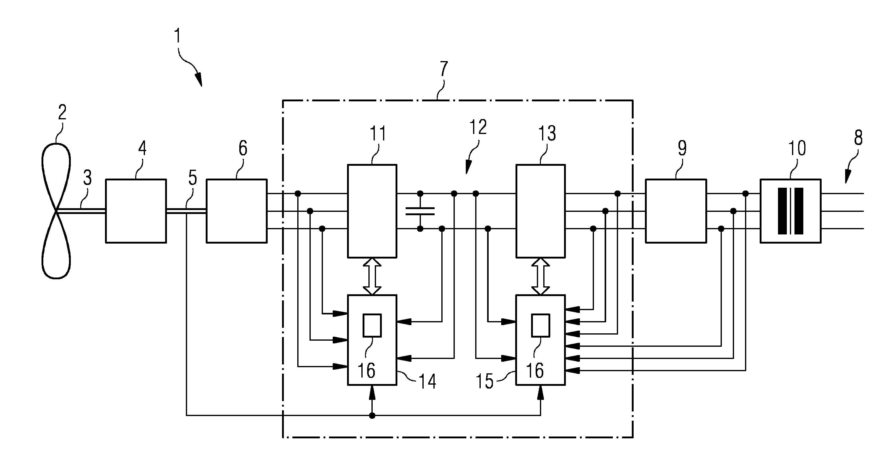
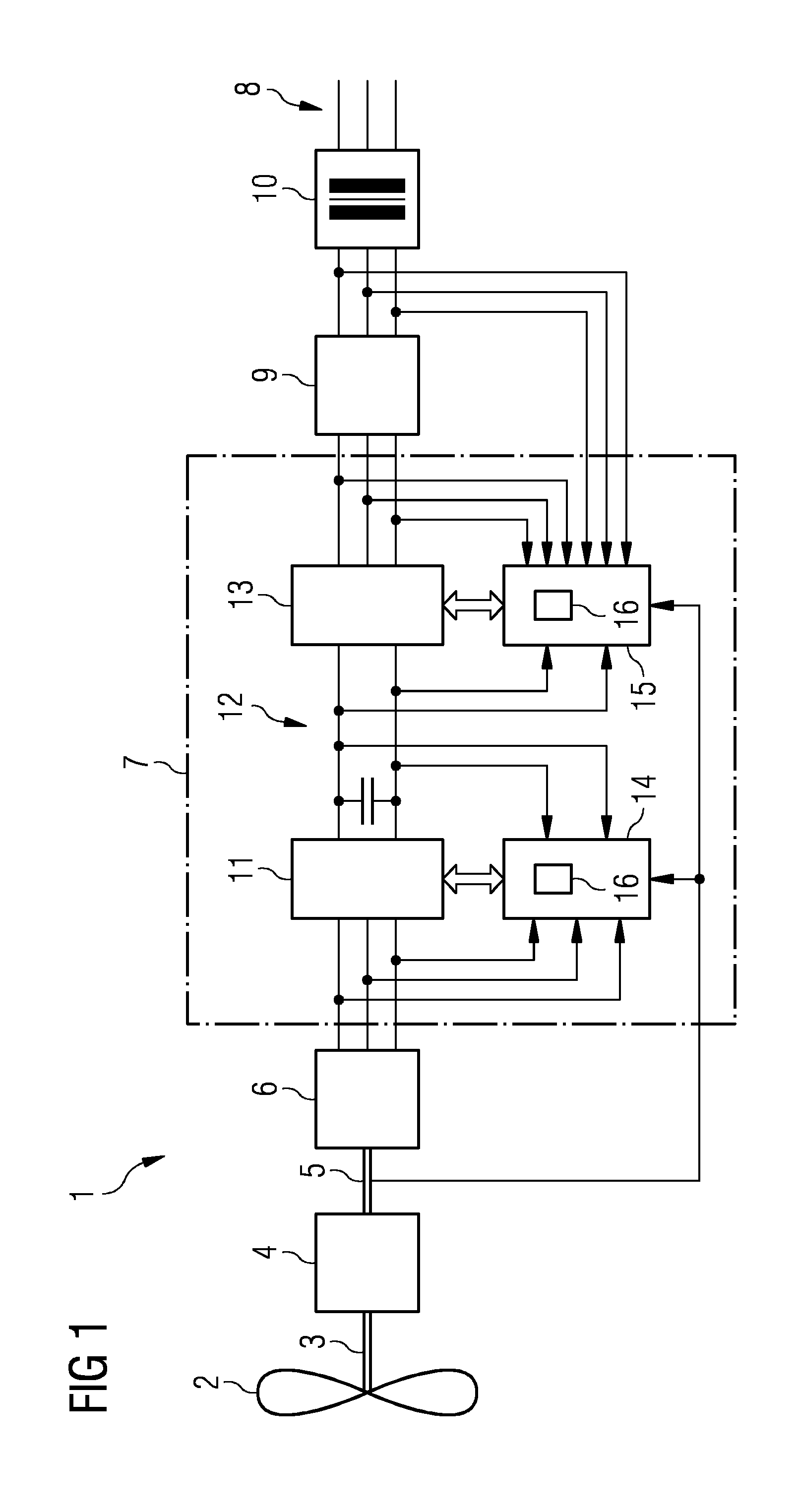
[0036]FIG. 1 shows an overview of the electrical components of an electrical energy generating apparatus like for example a wind turbine 1. The wind turbine 1 has a rotor 2 with one or more, usually three blades. The rotor 2 is arranged on a rotor shaft 3 which transmits the rotational momentum from the turning rotor 2 to a gearbox 4. The gearbox 4 transmits the rotation of the rotor shaft 3 to an output shaft 5 with a defined transmission ratio. For direct drive wind turbines,...


PUM


Abstract

A method for controlling a frequency converter is provided. The converter includes a rectifier, an inverter which is connected via a DC link to the rectifier, a rectifier controller and an inverter controller. A minimal rectifier DC link voltage for the rectifier controller is determined, a minimal inverter DC link voltage for the inverter controller is determined, a minimal DC link voltage as the maximum of the minimal rectifier DC link voltage and the minimal inverter DC link voltage is determined, and an optimal DC link voltage reference based on the minimum of the minimal DC link voltage and a maximal allowed DC link voltage is determined. The rectifier controller and/or the inverter controller is/are controlled based upon the optimal DC link voltage reference.

Description

CROSS REFERENCE TO RELATED APPLICATIONS[0001]This application claims priority of European Patent Office Application No. 11173989.2 EP filed Jul. 14, 2011. All of the applications are incorporated by reference herein in their entirety.FIELD OF INVENTION[0002]A method for controlling a frequency converter, a frequency converter and an electrical energy generating apparatus such as, for example a wind turbine, are provided. Moreover, an electric motor is provided. Particularly, optimisation of a DC link in a conversion of AC input power to AC output power is described.BACKGROUND OF INVENTION[0003]Wind turbines convert wind energy into electrical energy by using the force of the wind to drive the rotor of a generator. The generator generates AC power having a frequency which depends on the rotational speed of the rotor, i.e. to the wind force.[0004]Frequency converters or power converters may be used to convert AC power with a variable frequency as provided by the generator of a wind tu...

Claims


Application Information

Patent Timeline
Patent Type & Authority Applications(United States)
IPC IPC(8): H02M5/40
CPCH02M5/4585
Inventor DENG, HENG
Owner SIEMENS AG
Why Eureka
Try Eureka