Fatty tissue image display device

a display device and fatty tissue technology, applied in the field of fatty tissue image display devices, can solve the problems of difficult to objectively determine the degree to which the fatty liver progresses, and cannot be simply specified, so as to achieve easy diagnosis and easy to see the fat content.

Inactive Publication Date: 2013-01-17
ADVANTEST CORP +1
View PDF2 Cites 15 Cited by
  • Summary
  • Abstract
  • Description
  • Claims
  • Application Information

AI Technical Summary

Benefits of technology

[0032]According to the present invention, a tomographic image of the distribution of a change in the velocity of the ultrasonic waves where the distribution of the change in the velocity of the ultrasonic waves is expressed by luminance information or color information is displayed on the screen so that it waits for the designation of a region of interest (ROI) by the observer. When the region of interest is designated, data on the change in the velocity of the ultrasonic waves for each point within the region of interest is divided into data on a positive change in the velocity of the ultrasonic waves and data on a negative change in the velocity of the ultrasonic waves through the calculations for finding a histogram. The data on a positive change in the velocity of the ultrasonic waves is handled for the normal region, and the data on a negative change in the velocity of the ultrasonic waves is handled for the fat region so that they are used to calculate a fatty change index, which is an index of the proportion of fatty tissue.
[0033]As a result, the calculated fatty change index is displayed so that the degree to which a fatty change progresses in the region of interest can be displayed numerically and quantitatively, and thus, the fat region can be objectively evaluated.
[0034]So far, fatty tissue has been displayed with a color on the screen so that the fat content can be easily seen. However, quantification has been difficult for the fatty tissue in a marbled state, though the existence of fat can be confirmed. The present invention makes it possible to numerically output the fat content even for fatty tissue in a marbled state, and therefore, objective diagnosis can be easily achieved. In particular, a subject can be periodically and repeatedly measured so that a chronological change in the fat content can be recognized as a change in the numeric value, and thus, the effectiveness can be seen in diagnosing metabolic syndrome.Other Means for Solving the Problem and Effects
[0035]In the above-described invention, the region-of-interest designation unit may designate a region of interest so that the area of the designated region is constant.
[0036]Thus, a number of regions of interest where different locations are measured at different times can be compared so that the comparison in the degree of progress of a fatty change can be precise because regions of interest having the same area can be compared.
[0037]In the above-described invention, the fatty change index calculation unit may calculate the ratio of the area of the histogram of the fat region to that of the normal region as a fatty change index.

Problems solved by technology

However, it is not necessarily sufficient to simply specify the location of a region including fatty tissue for the actual diagnosis of a living body, but rather it is desirable for the proportion of the fatty tissue within the region to be objectively evaluated for diagnosis.
However, the proportion of the fatty tissue included in the specified regions (ratio of the number of cells of a fatty liver to that of a normal liver) cannot be measured, and therefore, it is difficult to objectively determine the degree to which the fatty liver progresses.

Method used


Image

  • Fatty tissue image display device
  • Fatty tissue image display device
  • Fatty tissue image display device

Examples


Embodiment Construction

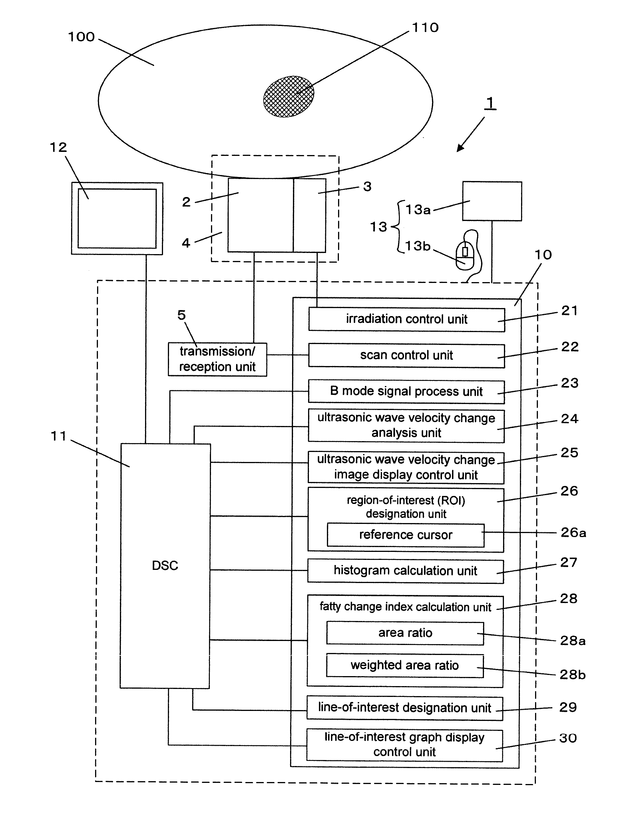
[0057]In the following, the fatty tissue image display device according to one embodiment of the present invention is described in reference to the drawings. Here, a target portion is heated through irradiation with infrared rays by means of an infrared ray laser used as a heating means.

[0058](Principle for Measurement of a Change in the Velocity of the ultrasonic waves)

[0059]First, the principle for measurement in an image of a change in the velocity of the ultrasonic waves displayed on the fatty tissue image display device is described below.

[0060]This data on the change in the velocity of the ultrasonic waves can be found from the following relationships.

[0061]FIG. 14 is a schematic diagram showing an ultrasonic wave echo signal when not irradiated with light and an ultrasonic wave echo signal after irradiation with light.

[0062]The velocity of the ultrasonic waves when not irradiated with light is V and the velocity of the ultrasonic waves after irradiation with light is V′. In a...


PUM


Abstract

Provided is a fatty tissue image display device capable of displaying an index indicating the degree of progress of fatty change. The fatty tissue image display device is provided with a light source (3), an ultrasonic wave transmission / reception mechanism (2, 5), an ultrasonic wave velocity change analysis unit (24) which calculates the change in the velocity of the ultrasonic waves after irradiation with a heating beam as compared to before irradiation with light, an ultrasonic wave velocity change image display control unit (25) which displays as a tomographic image the distribution of the calculated change in the velocity of the ultrasonic waves, a region-of-interest designation unit (26) which waits for the designation of a region of interest, a histogram calculation unit (27) which, on the basis of luminance information or color information within the designated region of interest, calculates the histograms of a fatty region showing a negative change in the velocity of the ultrasonic waves and a normal region showing a positive change in the velocity of the ultrasonic waves, and a fatty change index calculation unit (28) which, from the calculated histograms of the fatty region and the normal region, calculates a fatty change index that is the index of the proportion of fatty tissue.

Description

TECHNICAL FIELD[0001]The present invention relates to a device for displaying an image of fatty tissue within a living body using data of a change in the velocity of the ultrasonic waves after irradiating the living body with a heating beam, such as of light, electromagnetic waves or ultrasonic waves.BACKGROUND ART[0002]Diagnostic imaging devices include roentgen devices for X-ray photographs, X-ray CT devices, PET devices, MRI devices and diagnostic ultrasonic devices, each of which has good points and bad points in terms of the cost for installing the device, the ability to diagnose a certain body area, the time for examination, whether or not there is a problem of exposure to radiation, and whether or not a chemical needs to be injected, and thus, they are used for different purposes of examination.[0003]From among these diagnostic imaging devices, diagnostic ultrasonic devices and MRI devices are excellent with regards to safety because there are no problems of exposure to radia...

Claims


Application Information

Patent Timeline
Patent Type & Authority Applications(United States)
IPC IPC(8): A61B8/14A61B8/08A61F7/00
CPCA61B8/0858A61B5/4872A61B8/14A61B8/5223G16H50/30Y02A90/10
Inventor MATSUNAKA, TOSHIYUKIHORINAKA, HIROMICHIMORIKAWA, HIROYASUOGAWA, TOMOHIRO
Owner ADVANTEST CORP
Why Eureka
Try Eureka