Ventilation system for roof

a ventilation system and roof technology, applied in ventilation systems, lighting and heating apparatus, heating types, etc., can solve the problems of robbing the insulation of much of its r value, building with radiant barriers still having heat or moisture build-up in the attic, and the most common energy loss in a hom

Active Publication Date: 2013-01-24
ODANIELS LLC
View PDF6 Cites 24 Cited by
  • Summary
  • Abstract
  • Description
  • Claims
  • Application Information

AI Technical Summary

Problems solved by technology

One of the most common energy losses in a home is due to heat transfer through the attic.
In colder climates, moisture builds up in the a...

Method used


Image

  • Ventilation system for roof
  • Ventilation system for roof
  • Ventilation system for roof

Examples


Embodiment Construction

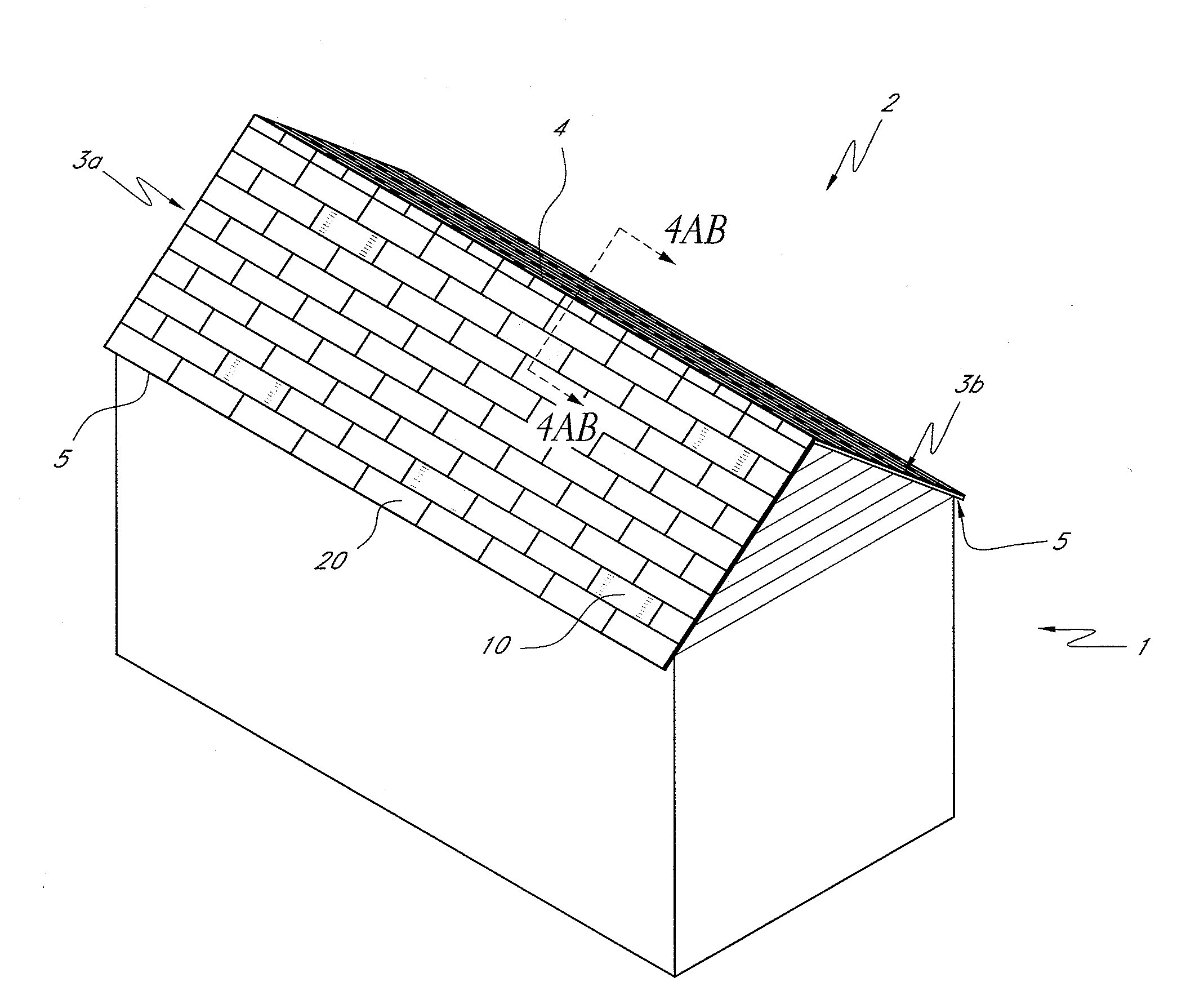
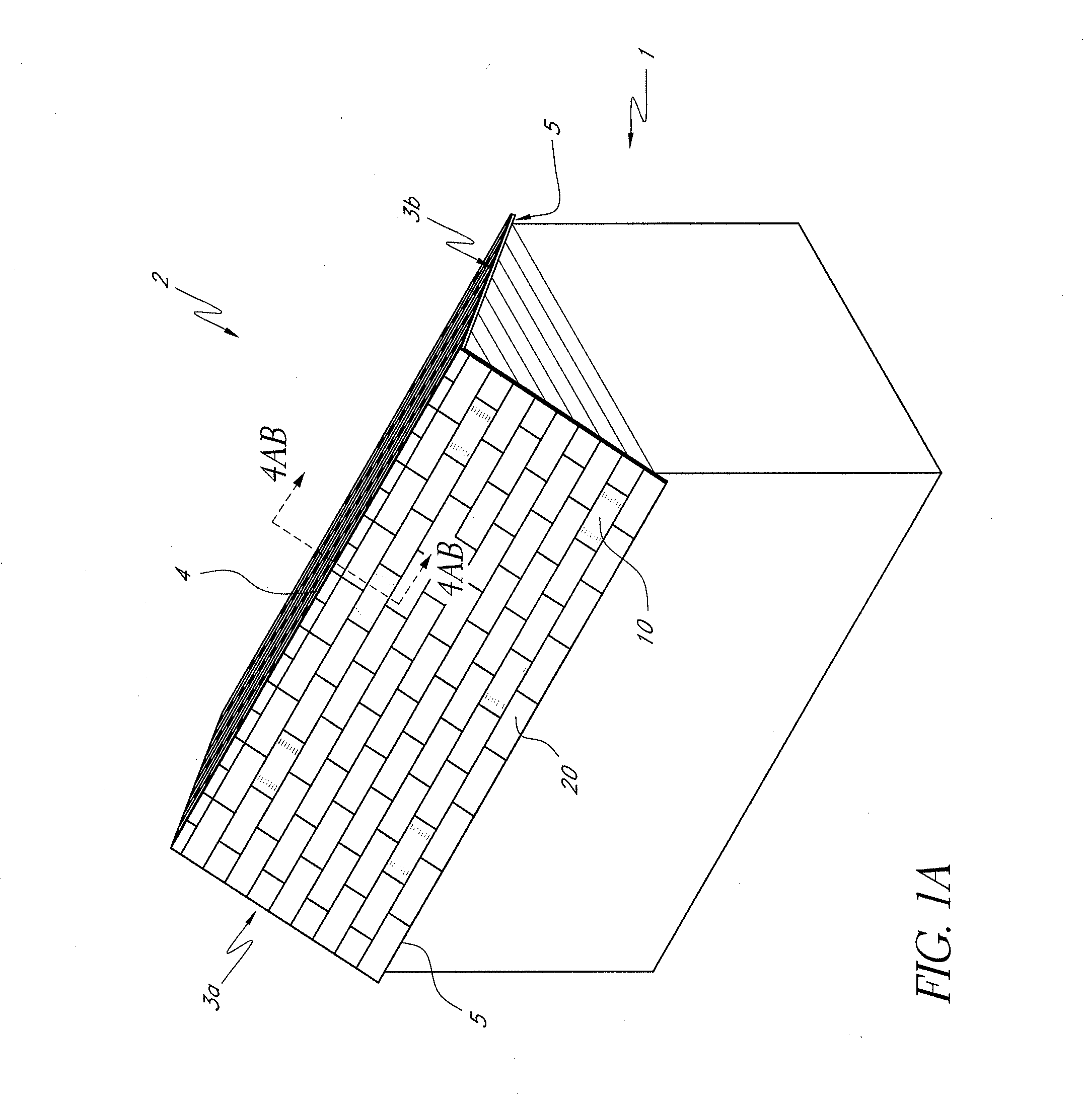
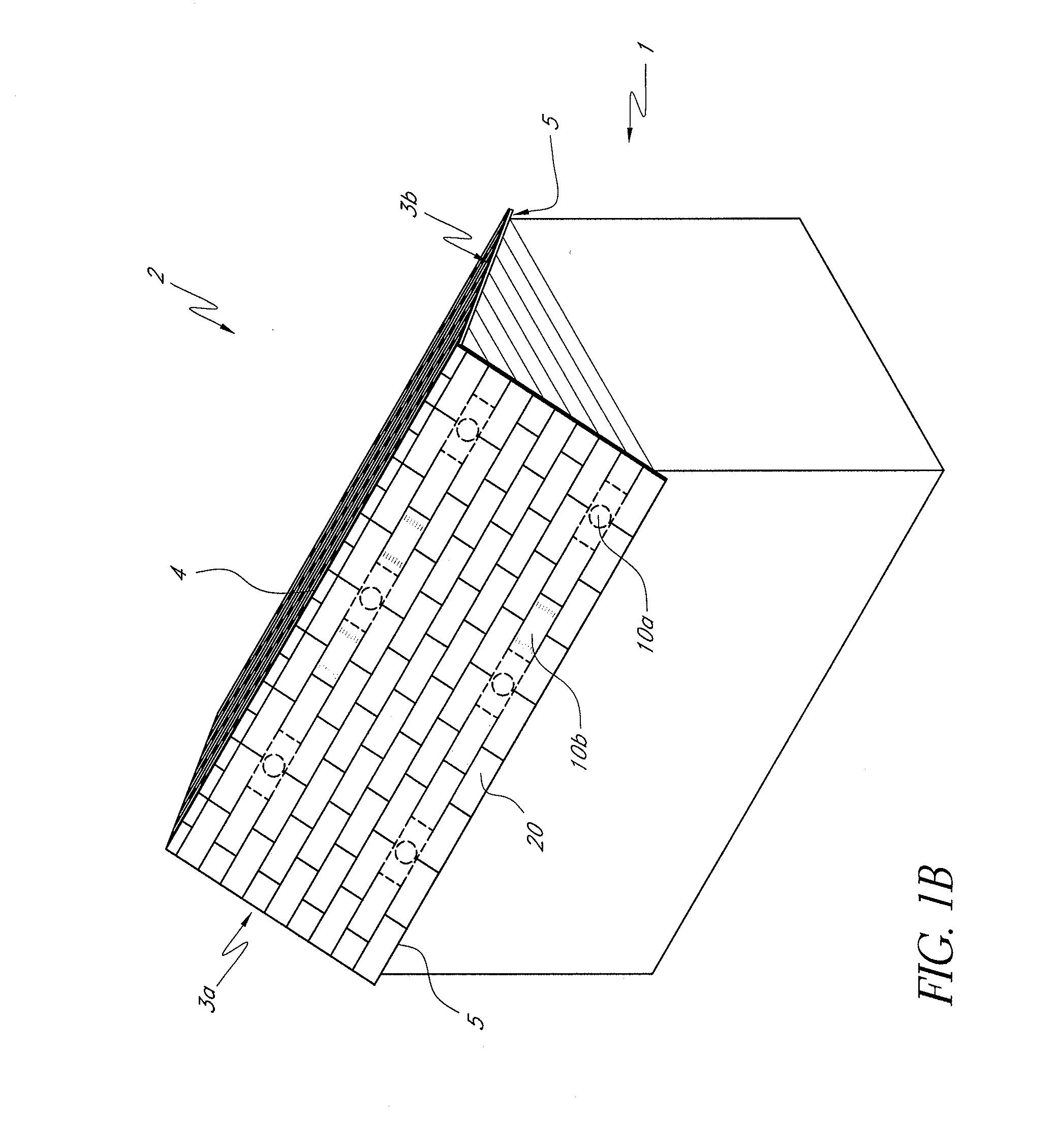
[0037]FIG. 1A shows a building 1 with a roof 2 comprising two fields 3a and 3b that are joined at their upper ends to define a ridge 4. Lower edges 5 of the fields are referred to as “eaves.” The fields 3a and 3b typically comprise a sheathing or roof deck covered with a layer of roof cover elements 20 such as tiles (e.g., clay, metal, or concrete), shingles (e.g., wooden, clay, asphalt, or composition), or sheeting (e.g., metal). The sheathing is typically supported by rafters (not shown). Along with roof cover elements 20, the fields 3a and 3b may also comprise a radiant barrier layer (not shown) and vent members 10. The illustrated roof is suitable for having one or more vent members 10 according to one embodiment of the invention. Also, skilled artisans will appreciate that the vent members may be provided in a wide variety of different types of roofs, including those not having ridges or sloped fields. In FIG. 1A, a plurality of substantially aligned vent members 10 is position...


PUM


Abstract

A roof vent and a roof structure are described. A roof vent can include a baffle with a cross-section where a first portion extends upward from a bottom plate and a second portion extends from the first portion to define a space between the bottom plate and the second portion. A roof structure may or may not have a roof deck, and comprises a plurality of roof cover elements with a radiant barrier layer underneath the top surfaces of at least some of the roof cover elements. In another embodiment, a roof structure may comprise more sheathing layer vent members than roof cover layer vent members. In yet another embodiment, a roof structure may comprise a layer of roof tiles with at least one vent member, the vent member comprising lateral end portions of a base member with a non-planar profile to engage a similar profile of an adjacent roof cover element.

Description

CROSS-REFERENCE TO RELATED APPLICATIONS[0001]This application claims priority as a non-provisional of U.S. Provisional Patent Application No. 61 / 321,474, filed Apr. 6, 2010, the entirety of which is incorporated herein by reference.BACKGROUND OF THE INVENTION[0002]1. Field of the Invention[0003]This application relates generally to building ventilation and specifically to roof ventilation.[0004]2. Description of the Related Art[0005]Energy efficiency is a serious consideration in new home design. New homes require ways to minimize energy requirements to maintain comfortable living spaces. One of the most common energy losses in a home is due to heat transfer through the attic. In warm climates, heat builds up in the attic from solar energy incident on the roof. In colder climates, moisture builds up in the attic, robbing the insulation of much of its R value. Early efforts at minimizing the effects of heat and / or moisture build-up focused on insulation between the living space and t...

Claims


Application Information

Patent Timeline
IPC IPC(8): E04D13/16E04D13/17
CPCE04D1/26E04D1/30E04D13/172F24F7/02E04D2001/309
Inventor DANIELS, GREGORY S.
Owner ODANIELS LLC
Why Eureka
Try Eureka