Tool and method for cleaning a drilled hole

a drilling hole and drilling technology, applied in the direction of cleaning hollow objects, brushes, applications, etc., can solve the problems of complete removal of drilling dust, and achieve the effect of simple and quick cleaning procedure, no dust generation, and extensive equipmen

Inactive Publication Date: 2013-01-24
HILTI AG
View PDF2 Cites 12 Cited by
  • Summary
  • Abstract
  • Description
  • Claims
  • Application Information

AI Technical Summary

Benefits of technology

[0008]It is an object of the present invention to provide a tool for cleaning a drilled hole that gets rid of drillings and drilling dust from an already finished drilled hole in a simple and quick cleaning procedure, without requiring extensive equipment and without generating much dust.
[0009]The present invention provides a tool for cleaning a drilled hole, with a tool shank that, relative to the shank axis, has an axial attachment end and an opposite axial cleaning end, as well as at least one conveying element for removing drilling dust from the drilled hole, said conveying element being attached to the tool shank and arranged in the axial direction like a helix around the tool shank and being configured as a channel that is open in the direction of the attachment end. Such a helical channel can very simply and efficiently remove drillings and drilling dust from the bottom of the drilled hole, in the manner of a corkscrew (twisted into the drilled hole), in combination with an Archimedean screw (after having been twisted into the drilled hole). According to the invention, the helical channel can be configured to be right-handed or left-handed.
[0010]In one embodiment of the tool, the conveying element is configured as a conveyor belt with a continuous, especially dust-impermeable transport surface. This continuous conveyor belt—unlike brush elements—prevents the drilling dust from trickling down towards the bottom of the drilled hole.

Problems solved by technology

Moreover, the blown-out drilling dust causes considerable dust pollution and is thus a health concern for the workers doing the job.
Although the radially protruding brush elements provided make it possible to clean adhering drilling dust off the wall of the drilled hole, they do not completely remove the drilling dust that has been loosened and that has accumulated at the bottom of the drilled hole, since the loose material can fall through the brush down towards the bottom of the drilled hole, especially if the brush rubs against the wall of the drilled hole when the drilling tool makes a rotating motion.

Method used


Image

  • Tool and method for cleaning a drilled hole
  • Tool and method for cleaning a drilled hole
  • Tool and method for cleaning a drilled hole

Examples


first embodiment

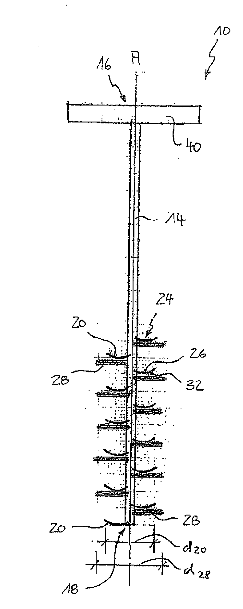
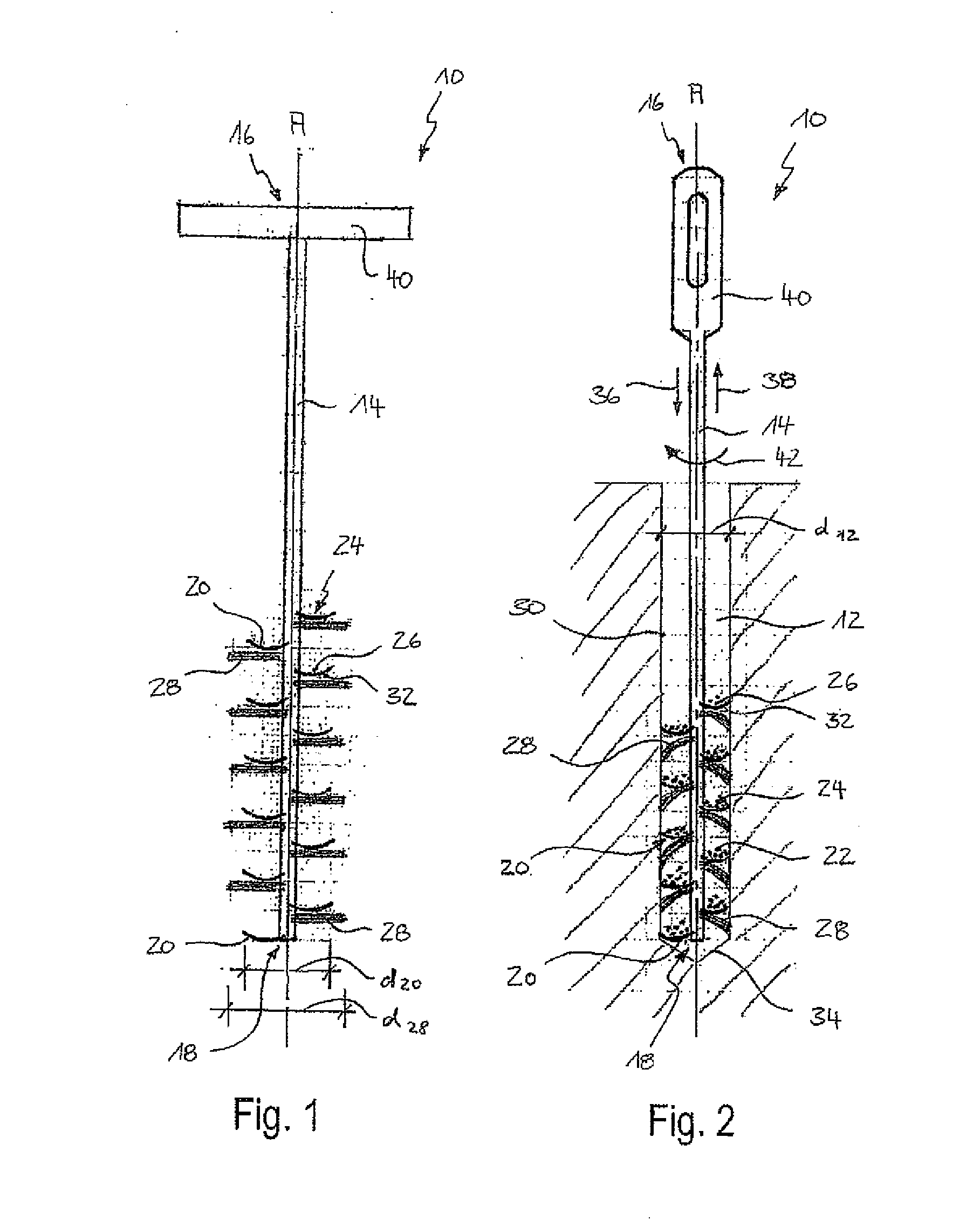
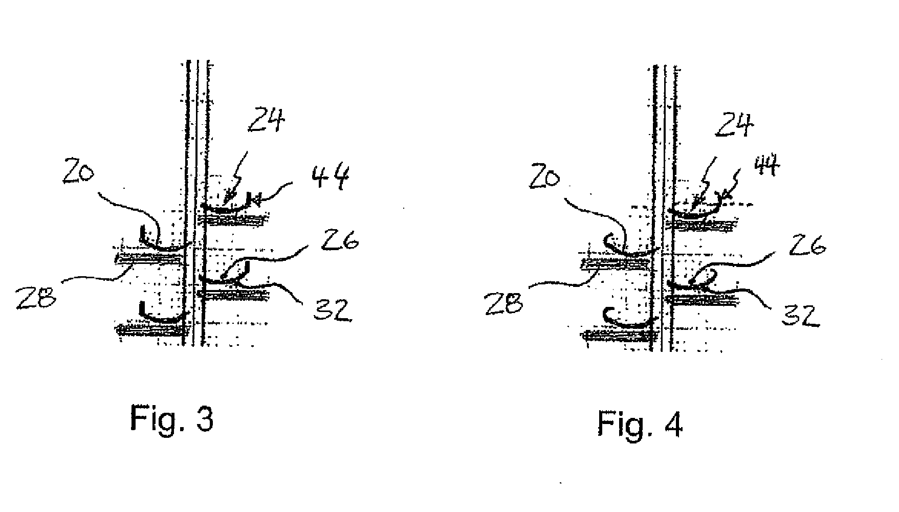
[0034]FIG. 1 shows a tool 10 for cleaning a drilled hole 12 (see FIG. 2), with a tool shank 14 that, relative to a shank axis A, has an axial attachment end 16 and an opposite axial cleaning end 18, as well as at least one conveying element 20 for removing drilling dust 22 (and drillings) from the drilled hole 12, said conveying element 20 being attached to the tool shank 14 and arranged in the axial direction like a helix around the tool shank 14 and being configured as a channel 24 that is open in the direction of the attachment end 16.

[0035]The conveying element 20 can be a conveyor belt with a continuous dust-impermeable transport surface 26, whereby a lengthwise edge of the helical conveying element 20 is adjacent to the tool shank 14, and it is preferably in contact with the tool shank 14 or engages with the tool shank 14. Furthermore, the lengthwise edge of the conveying element 20 is joined to the tool shank 14, at least in sections, for example, welded, glued, screwed or he...

second embodiment

[0042]FIG. 2 shows the tool 10 whereby the cleaning end 18 of the tool shank 14 have already been inserted axially into the drilled hole 12 (arrow 36), and, in the snapshot shown in FIG. 2, it is being pulled back out of the drilled hole 12 in the opposite axial direction (arrow 38).

[0043]The second embodiment of the tool 10 as shown in FIG. 2 is identical to the first embodiment of the tool 10 as shown in FIG. 1, except for an actuation device 40 on the attachment end 16 of the tool shank 14.

[0044]Whereas a handle for manually actuating the tool 10 is provided in FIG. 1, the actuation device 40 as shown in FIG. 2 is formed by a defined positive fit contour that, for example, can fit positively into the socket of a power drill or that can fit non-positively into the socket of an electric-powered screwdriver, in order to mechanically actuate the tool 10.

[0045]First of all, the drilled hole 12 is made with a prescribed hole diameter d12, whereby this hole diameter d12 is smaller than...


PUM


Abstract

A tool (10) for cleaning a drilled hole (12), including a tool shank (14) that, relative to the shank axis (A), has an axial attachment end (16) and an opposite axial cleaning end (18), as well as at least one conveying element (20) for removing drilling dust (22) from the drilled hole (12). The conveying element (20) is attached to the tool shank (14) and arranged in the axial direction like a helix around the tool shank (14). The conveying element (20) is configured as a channel (24) that is open in the direction of the attachment end (16). A method for cleaning a drilled hole by such a tool (10) is also disclosed.

Description

[0001]This claims the benefit of German Patent Application DE 10 2010 063 859.5 filed Dec. 22, 2010 and hereby incorporated by reference herein.[0002]The invention relates to a tool as well as to a method for cleaning a hole drilled in materials that are preferably and commonly used in construction.BACKGROUND[0003]When an add-on part is to be subsequently attached to an existing structure, a hole is often drilled and a fastening element is anchored in this hole. The hole is normally created using a drill. In this process, loose material (drillings and drilling dust) remains in the hole drilled in construction materials such as concrete, natural stone or solid brick, whereby the amount of material depends on the size of the drilled hole as well as on the drilling angle (e.g. vertically downwards, horizontal or vertically upwards), and this takes up about 5% to 25% of the drilled hole volume in the case of holes that are drilled vertically downwards or horizontal.[0004]The drillings a...

Claims


Application Information

Patent Timeline
Patent Type & Authority Applications(United States)
IPC IPC(8): B08B9/027
CPCA46B5/02A46B9/06A46B13/006B28D7/02A46B2200/3013B08B1/00B08B9/00A46B15/0002
Inventor GINTER, HERBERT
Owner HILTI AG
Why Eureka
Try Eureka