
Roller with spray-coated surface structure

a surface structure and roller technology, applied in the direction of web handling, pile separation, transportation and packaging, etc., can solve the problems of high labor and time consumption, idling of the roller, and increasing not only the manufacturing cost but also the manufacturing process of the roller, so as to increase the surface friction and wear resistance

Inactive Publication Date: 2007-03-15
YANMO ENTERPRISE
View PDF2 Cites 1 Cited by
  • Summary
  • Abstract
  • Description
  • Claims
  • Application Information

AI Technical Summary

Benefits of technology

[0005] A primary object of the present invention is to provide a roller with spray-coated surface structure, in which liquid polyester is used as a medium to achieve an even and stable coating of a mixture of polyester and powder over the roller through simple and quick procedures.
[0006] Another object of the present invention is to provide a roller with spray-coated surface structure that can be achieved without consuming too much energy.
[0008] The roller with spray-coated surface structure so produced has increased surface friction and wear-resistance, and is therefore very suitable for push feeding sheet material.

Problems solved by technology

Most of the conventional rollers are produced to have a smooth outer circumferential surface that provides insufficient frictional force in push feeding the sheet material and results in idling of the roller.
This solution is highly labor and time consuming, particularly for a metal roller.
However, the putting of the rubber sleeve over the roller increases not only the manufacturing cost but also the manufacturing process of the roller.
Moreover, the rubber sleeve has low thermal plasticity and durability, and tends to become worn out or hardened after being used over a prolonged time, preventing the roller from stably push feeding the sheet material.

Method used


Image

  • Roller with spray-coated surface structure
  • Roller with spray-coated surface structure

Examples


Embodiment Construction

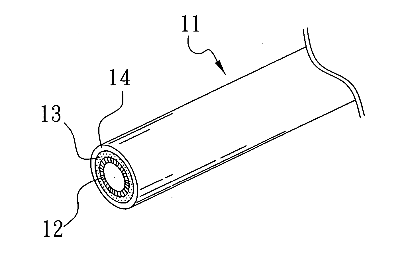
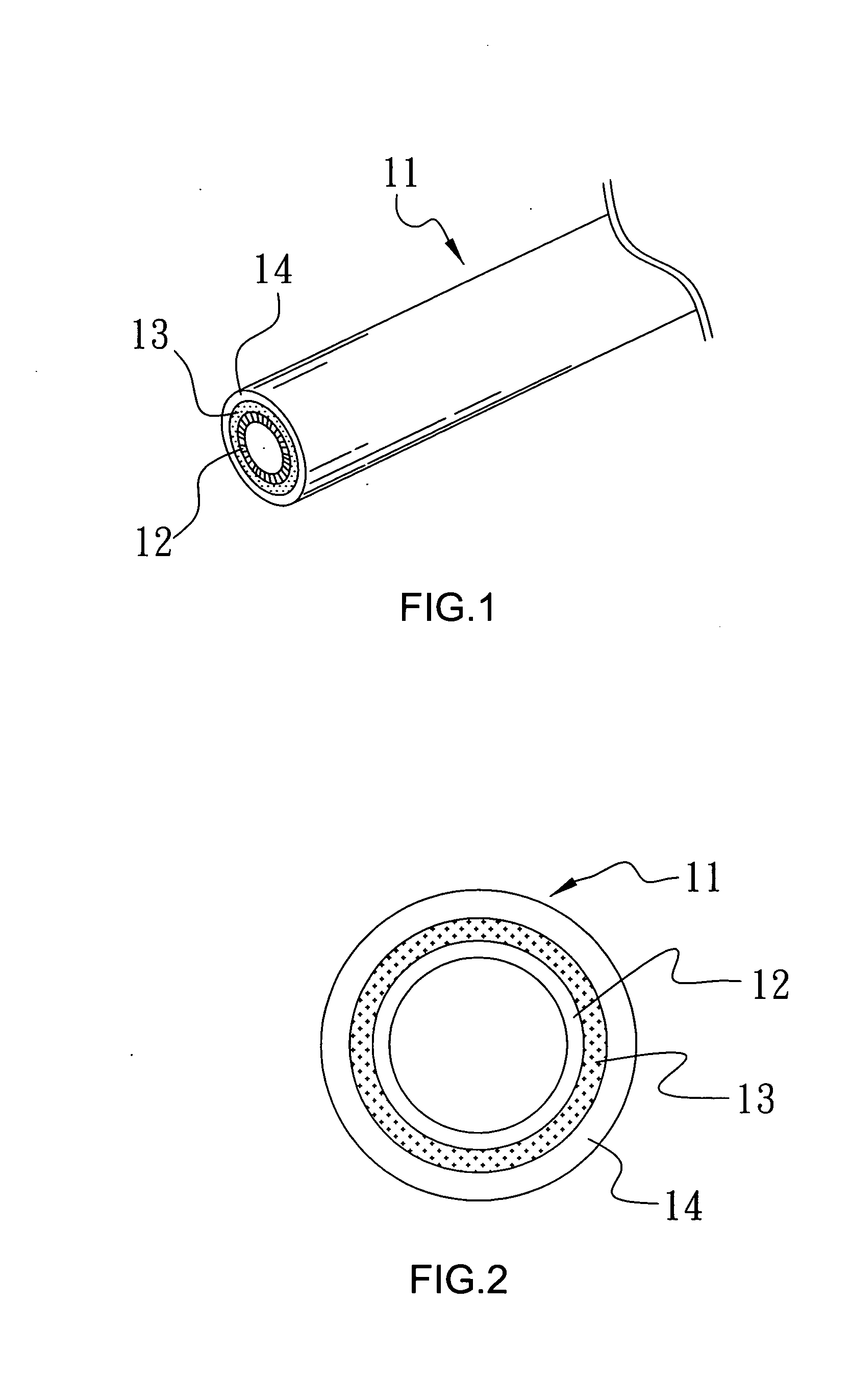
[0012] Please refer to FIGS. 1 and 2 that are perspective and cross-sectional views, respectively, of a roller with spray-coated surface structure according to the present invention. As shown, the roller is made of a metal material and generally denoted with a reference numeral 11. An outer circumferential surface of the metal roller 11 is subjected to coarsening, so as to form a coarsened layer 12. An outer circumferential surface of the coarsened layer 12 is subjected to a predetermined surface finishing, such as metal plating, metal spraying, etc., so as to form a finished layer 13 to increase the life, the wear-resistance, and the smoothness of the roller 11. A frictional layer 14 is further formed over the finished layer 13 to largely increase the surface friction of the roller 11, so that the roller 11 is suitable for use as a feeding roller in a printer, a photocopier, etc. to push feed sheets of paper.

[0013] The frictional layer 14 is formed by way of heating the roller 11 ...


PUM

PropertyMeasurementUnit
temperatureaaaaaaaaaa
surface structureaaaaaaaaaa

Abstract

A roller has a spray-coated surface structure that provides the roller with an increased surface friction, so that the roller is suitable for push feeding sheet material. The spray-coated surface structure includes a coarsened layer, a finished layer, and a frictional layer provided on an outer circumferential surface of the roller from inner to outer side. The frictional layer is formed by mixing predetermined amount of liquid polyester with predetermined amount of silicon carbide powder and / or alumina oxide powder at normal temperature and pressure, evenly spraying the mixture over the roller, heating the roller for the mixture to set on the outer surface of the roller, and allowing the roller to cool.

Description

FIELD OF THE INVENTION [0001] The present invention relates to a roller with spray-coated surface structure, and more particularly to a roller that is subjected to a predetermined surface finishing and heating, and is then evenly sprayed with a mixture of liquid polyester and powder to obtain an increased surface friction. BACKGROUND OF THE INVENTION [0002] A roller is an important element frequently used in different machines to push feed sheet material. For example, a roller is frequently used in a printer, a photocopier, and many other office machines to roll on a top of a stack of sheet paper, so as to push and feed the sheet paper at the highest position of the stack. [0003] Most of the conventional rollers are produced to have a smooth outer circumferential surface that provides insufficient frictional force in push feeding the sheet material and results in idling of the roller. One of the conventional ways to solve this problem is to form patterns on the roller by engraving t...

Claims


Application Information

Patent Timeline
Patent Type & Authority Applications(United States)
IPC IPC(8): B65H3/06B65H5/02B65H29/20
CPCB65H27/00B65H2404/185B65H2404/18B65H2401/114
Inventor LIN, LEI-HSIANG
Owner YANMO ENTERPRISE
Learn More