Thermal module structure and manufacturing method thereof

a technology of thermal modules and manufacturing methods, applied in the direction of manufacturing tools, semiconductor/solid-state device details, lighting and heating apparatus, etc., can solve the problems of increasing manufacturing costs, inability to use screws to fix heat pipes, and inability to efficiently conduct heat, etc., to achieve better heat conduction effect and more flexibility in assembly

Inactive Publication Date: 2013-01-24
ASIA VITAL COMPONENTS SHENZHEN CO LTD
View PDF9 Cites 11 Cited by
  • Summary
  • Abstract
  • Description
  • Claims
  • Application Information

AI Technical Summary

Benefits of technology

[0017]By means of the manufacturing method of the thermal module structure of the present invention, the heat dissipation components of

Problems solved by technology

However, as to aluminum-made heat dissipation components, it is necessary to use specific brazing means for brazing the heat dissipation components with each other.
This leads to increase of manufacturing cost.
However, the fastening members can be only used to lock some heat dissipation components (such as radiating fin assembly and heat dissipation base), while it is impossible to use screws to fix the heat pipe.
However, a gap exists between the heat pipe and the heat dissipation base to lead to thermal resistance against transfer from the heat dissipation base to the heat pipe.
Under such ci

Method used


Image

  • Thermal module structure and manufacturing method thereof
  • Thermal module structure and manufacturing method thereof
  • Thermal module structure and manufacturing method thereof

Examples


first embodiment

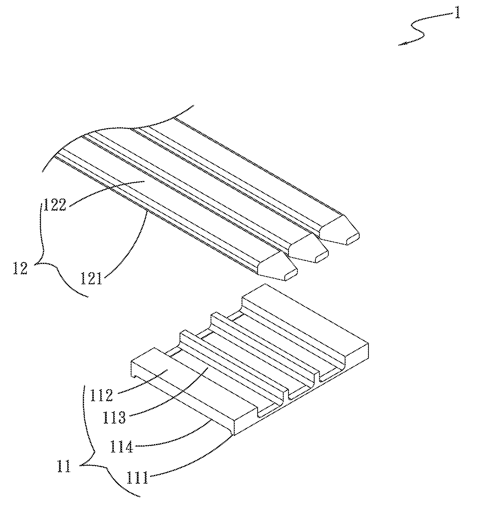
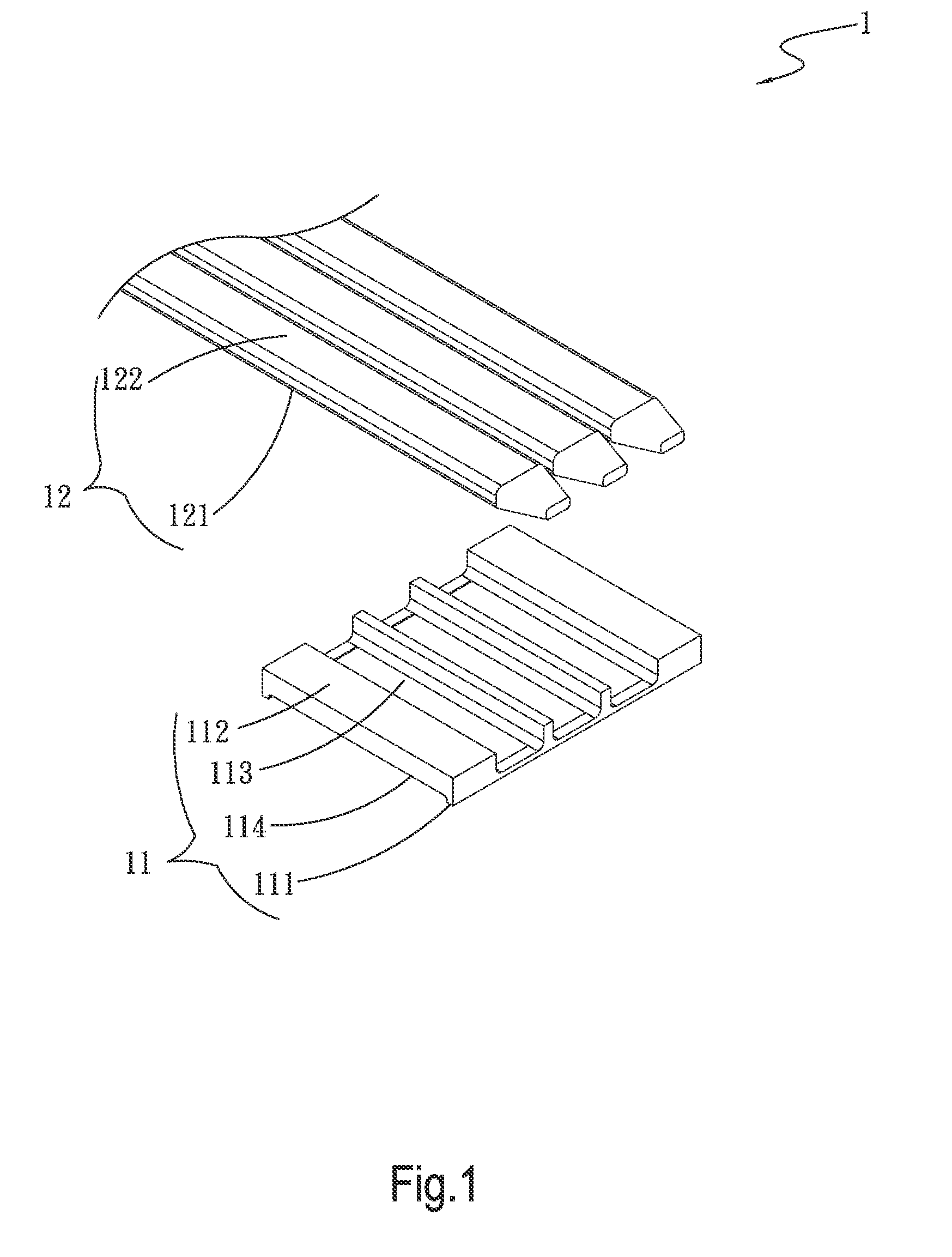
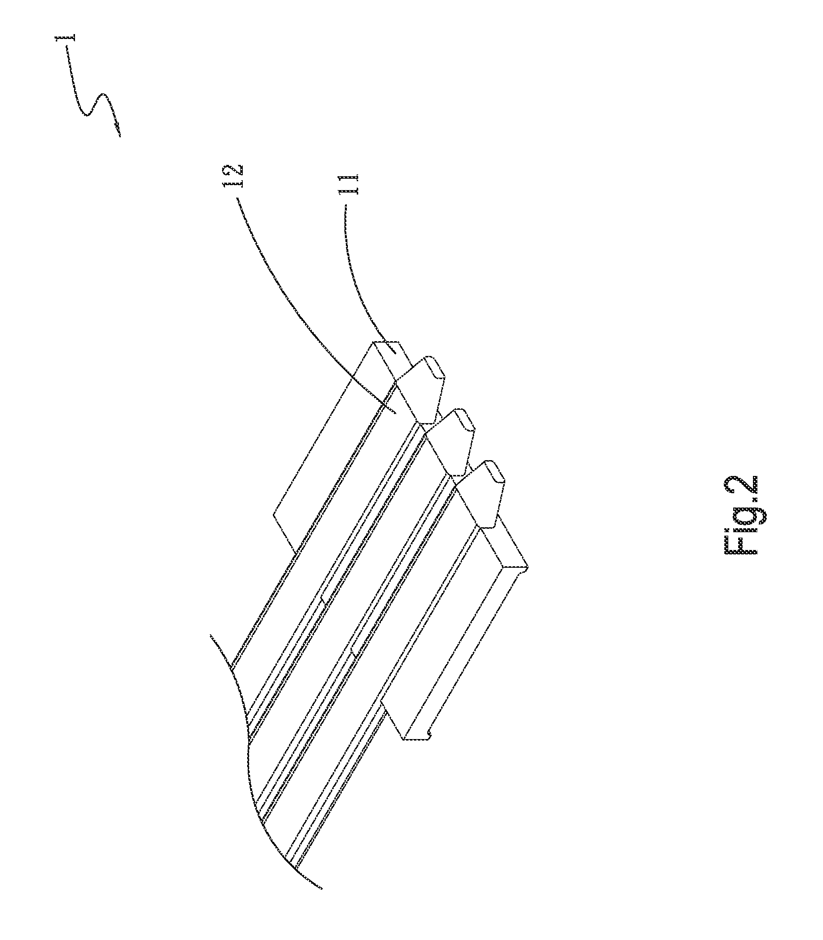
[0041]Please refer to FIG. 11, which is a flow chart of the manufacturing method of the thermal module structure of the present invention. Also referring to FIGS. 1 and 2, the manufacturing method of the thermal module structure of the present invention includes steps of:

S1: preparing at least one heat pipe and a base having at least one channel, a heat pipe 12 and a base 11 with at least one channel (the first channel 113) being prepared;

S2: correspondingly disposing the heat pipe into the channel of the base, at least one end of the heat pipe 12 being correspondingly pressed into the channel (the first channel 113) of the base 11 to connect with the base 11; and

S3: forming a recessed section on one side of the base opposite to the channel by means of mechanical processing, the recessed section being in communication with the channel, a recessed section (the first recessed section 114) being formed on the other side of the base 11 opposite to the channel (the first channel 113) by ...

second embodiment

[0042]Please refer to FIG. 12, which is a flow chart of the manufacturing method of the thermal module structure of the present invention. Also referring to FIGS. 1 to 6, the manufacturing method of the thermal module structure of the present invention includes steps of:

S1: preparing at least one heat pipe and a base having at least one channel;

S2: correspondingly disposing the heat pipe into the channel of the base; and

S3: forming a recessed section on one side of the base opposite to the channel by means of mechanical processing, the recessed section being in communication with the channel.

[0043]The second embodiment of the manufacturing method of the thermal module structure of the present invention is substantially identical to the first embodiment and thus will not be repeatedly described hereinafter. The second embodiment is different from the first embodiment in that after step S2 of correspondingly disposing the heat pipe into the channel of the base, the second embodiment f...


PUM

PropertyMeasurementUnit
Widthaaaaaaaaaa
Thermal propertiesaaaaaaaaaa

Abstract

A thermal module structure and a manufacturing method thereof. The thermal module structure includes a base and a heat pipe. The base has a first channel and a first recessed section in communication with the first channel. The heat pipe is correspondingly disposed in the first channel. According to the thermal module structure, the heat pipe can directly contact heat source and directly connect with the base without brazing. Therefore, the manufacturing cost is greatly lowered.

Description

BACKGROUND OF THE INVENTION[0001]1. Field of the Invention[0002]The present invention relates generally to a thermal module structure and a manufacturing method thereof. The thermal module structure includes a base and a heat pipe. According to the manufacturing method, the heat pipe can be directly assembled with the base to contact heat source without the conventional brazing process.[0003]2. Description of the Related Art[0004]A conventional heat dissipation device or thermal module is composed of multiple heat dissipation components assembled with each other. The heat dissipation components are heat pipes, heat sinks, heat dissipation bases, etc. These heat dissipation components are generally fixedly connected with each other by means of brazing. However, as to aluminum-made heat dissipation components, it is necessary to use specific brazing means for brazing the heat dissipation components with each other. This leads to increase of manufacturing cost.[0005]Alternatively, the ...

Claims


Application Information

Patent Timeline
IPC IPC(8): F28D15/04B23P19/00
CPCB23P2700/09B23P15/26F28D15/0233F28D15/0275H01L23/4006Y10T29/49826H01L2924/0002H01L23/427Y10T29/49353H01L2924/00F28F13/00
Inventor WU, CHUN-MING
Owner ASIA VITAL COMPONENTS SHENZHEN CO LTD
Why Eureka
Try Eureka