Flexible Truss Frame and Method of Making the Same

a truss frame and flexible technology, applied in the field of composite structures, can solve the problems of increasing the cost and complexity of some applications, affecting joint strength, stiffness and/or durability, time-consuming shimming, etc., to reduce the number of unique parts and associated recurring and non-recurring costs, reduce stress concentration, and reduce the effect of total part coun

Active Publication Date: 2013-01-24
THE BOEING CO
View PDF4 Cites 50 Cited by
  • Summary
  • Abstract
  • Description
  • Claims
  • Application Information

AI Technical Summary

Benefits of technology

[0007]The disclosed embodiments provide a structural frame suitable for stiffening primary and secondary structures, particularly composite structures. The frame comprises a combination of truss elements and a continuous cap arranged to form articulations along the length of the frame which allow the frame to flex or bend during installation. Flexing of the frame allows it to conform to local surface contours of a structure during installation, however, the frame provides required rigidity in all planes after it is attached to the structure. The degree of flexibility of the frame may be readily tailored to suit the requirements a particular application. The flexibility of the frame allows it to be manufactured as a standardized common part that may be used in multiple locations, thereby significantly reducing the number of unique parts and associated recurring and nonrecurring costs. The frame may be fastened to a contoured surface without shimming, using typical assembly installation forces. The disclosed frame may reduce total part count, and may reduce stress concentrations in the area of intersecting longitudinal stiffening elements.

Problems solved by technology

Conventional stiffening elements may have characteristics which increase their cost and complexity in some applications.
Shimming is time consuming and may require complex geometric shim shapes which may affect joint strength, stiffness and / or durability.
The design of lateral stiffening elements in airframes may also be complicated by the need to span intersecting stiffeners such as longitudinal hat stiffeners and blade stiffeners.
Mouseholes add complexity to the manufacturing process and may result in undesirable stress concentrations in the airframe.

Method used


Image

  • Flexible Truss Frame and Method of Making the Same
  • Flexible Truss Frame and Method of Making the Same
  • Flexible Truss Frame and Method of Making the Same

Examples


Embodiment Construction

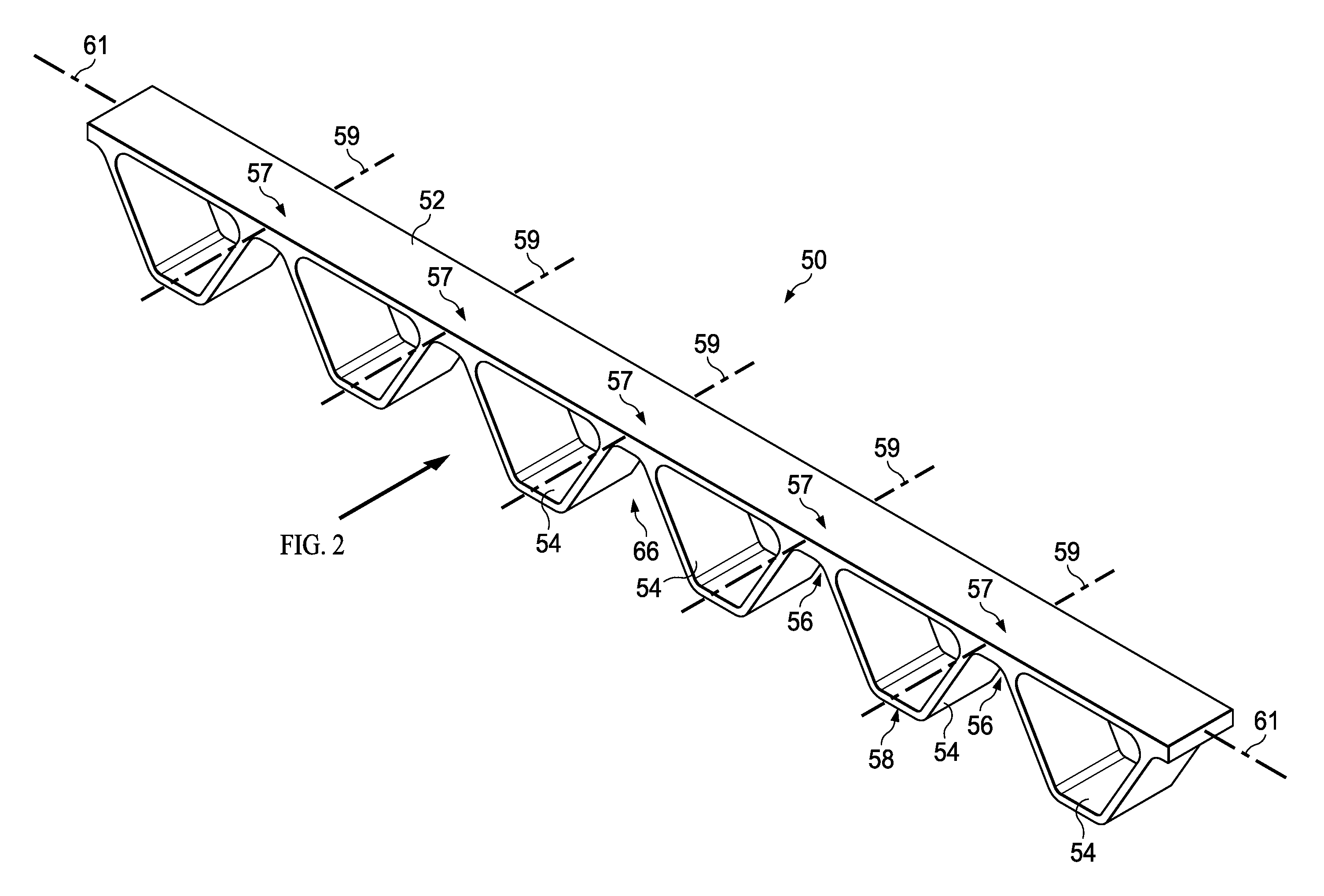
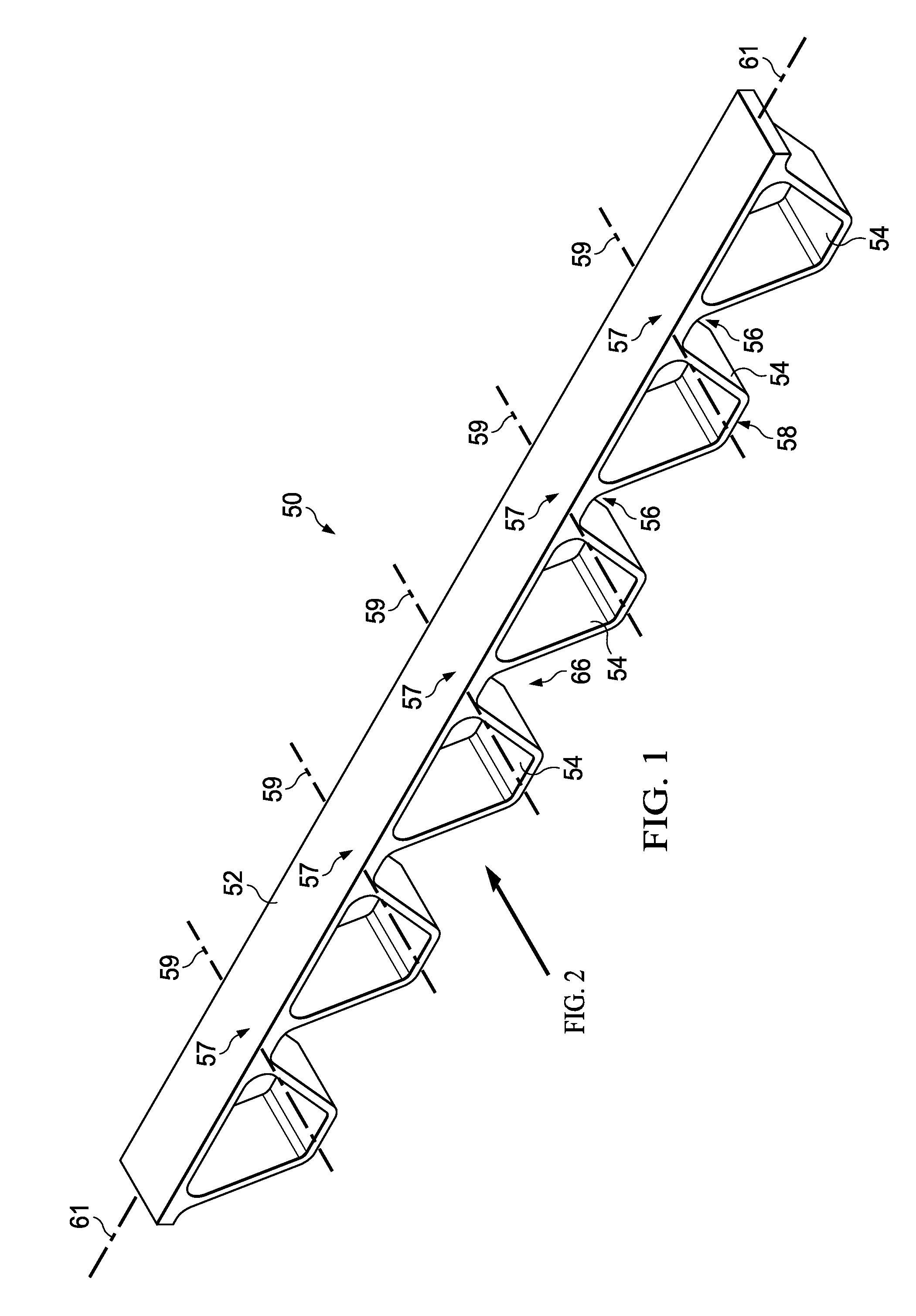
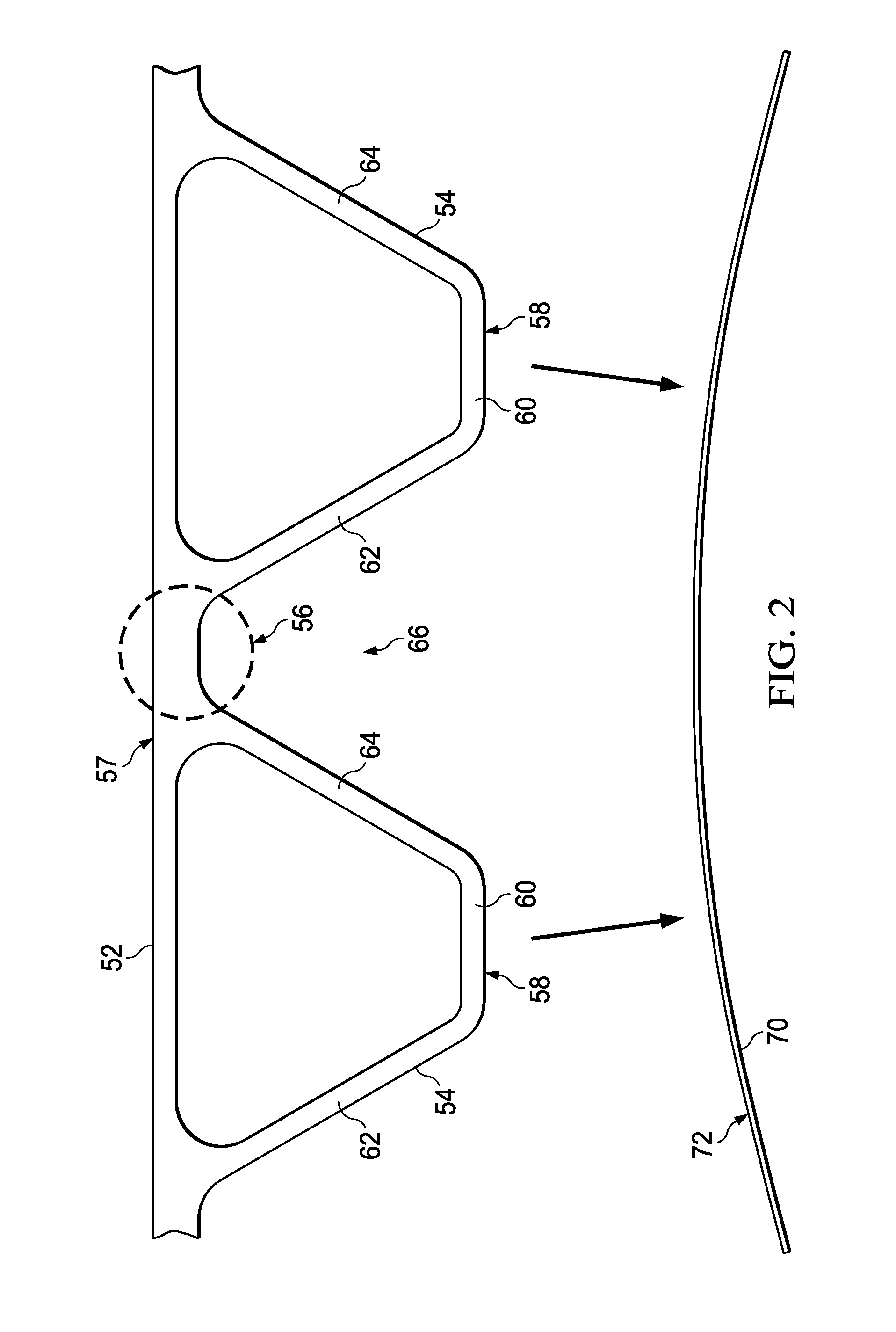
[0041]Referring first to FIGS. 1 and 2, the disclosed embodiments relate to a flexible truss frame 50 suitable for use in primary and secondary structures, such as the skin 70 covering an airframe (FIG. 8). As will be discussed below in more detail, the frame 50 may be formed of composite materials and is flexible along its length during the installation process so as to conform to local contours of the surface 72 of the skin 70. The flexibility of the frame 50 allows it to be manufactured as a common part that fits-up to differing contours of the skin surface 72. Although the frame 50 is flexible under typical assembly forces to conform to local contours of the skin surface 72, the frame 50 provides the required stiffness and rigidity after it is attached to the skin 70. It should be noted here that while an airframe skin 70 has been disclosed for illustrative purposes, the flexible frame 50 may be employed to stiffen a wide range of other primary and secondary structures used in a...


PUM

PropertyMeasurementUnit
flexibleaaaaaaaaaa
rigidityaaaaaaaaaa
lengthaaaaaaaaaa

Abstract

A composite frame includes a plurality of truss elements covered by a cap. The truss elements are flexibly coupled with each other and with the cap. The frame flexes to conform to a contoured surface to which it is attached. Once attached, the installed frame provides the required rigidity to the structure.

Description

BACKGROUND INFORMATION[0001]1. Field:[0002]The present disclosure generally relates to composite structures, and deals more particularly with a flexible truss frame for stiffening structures, as well as a method of making the frame.[0003]2. Background:[0004]Structures such as airframes typically contain a number of lateral stiffening elements such as frames and ribs at regular intervals along the length of the structure. Conventional stiffening elements may have characteristics which increase their cost and complexity in some applications. For example, each of the lateral stiffening elements in an airframe may require a unique inner mold line surface contour in order to conform to a skin at each location along the airframe. Thus, each of the stiffening elements is a unique part.[0005]Rigid stiffening elements often require shimming during the assembly process to accommodate buildup of manufactured tolerances. Shimming is time consuming and may require complex geometric shim shapes w...

Claims


Application Information

Patent Timeline
Patent Type & Authority Applications(United States)
IPC IPC(8): B64C1/00B21D53/88B32B3/28
CPCB64C1/061B64C2001/0072B64C2001/0081Y10T29/49622B32B37/1284B32B37/18Y10T428/24669Y02T50/433Y02T50/40
Inventor GLYNN, ANDREW K.GEORGIADIS, STEVEPOOK, DAVID ANDREW
Owner THE BOEING CO
Why Eureka
Try Eureka