
Gripper Claw with Replaceable Gripper Fingers

Active Publication Date: 2013-01-24
TECAN TRADING AG
View PDF5 Cites 20 Cited by
  • Summary
  • Abstract
  • Description
  • Claims
  • Application Information

AI Technical Summary

Benefits of technology

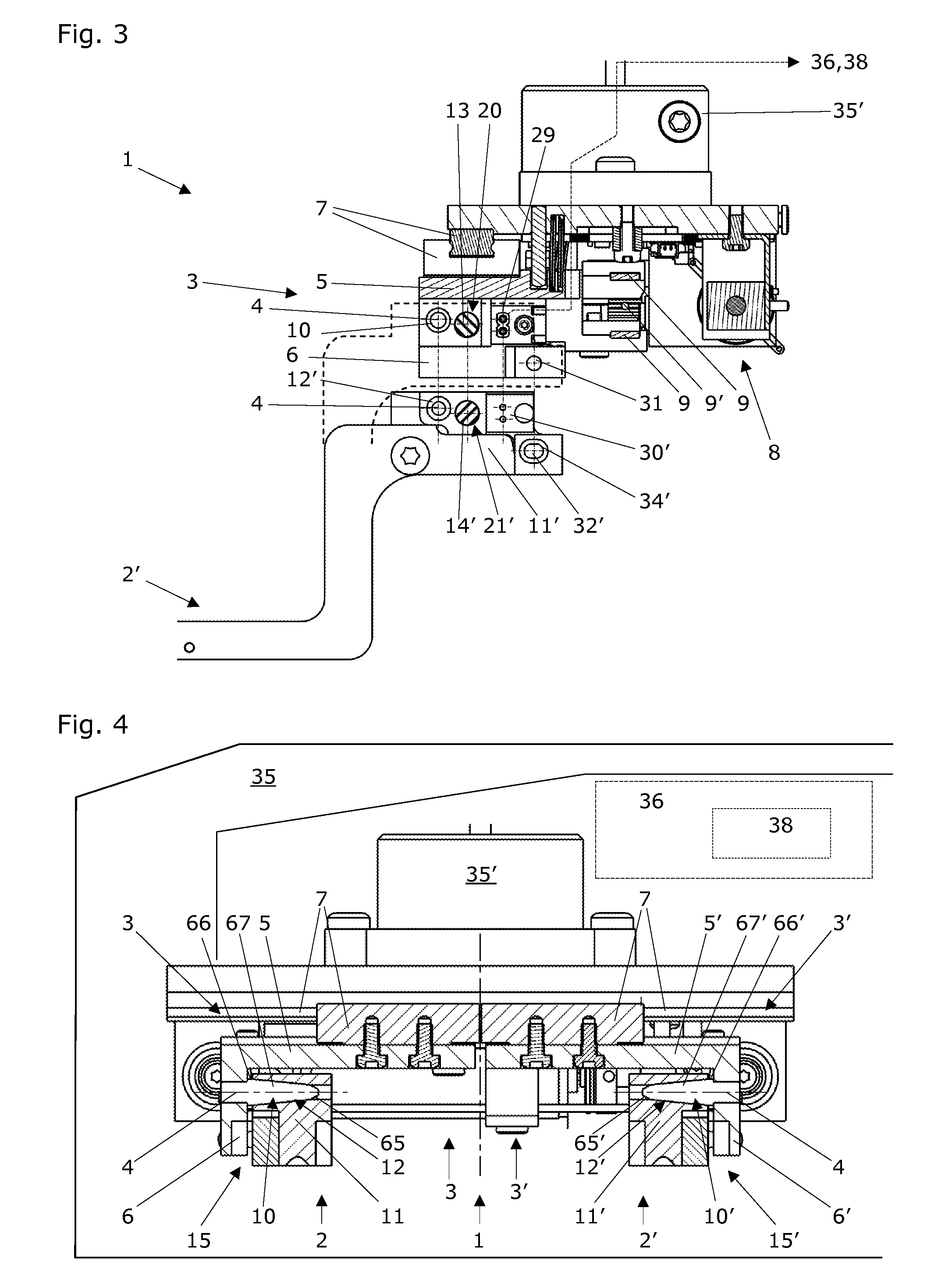
The gripper claw / gripper finger combination described in this patent has several features that prevent the gripper fingers from tilting during use. First, there are holding means that hold the gripper fingers in a stop position on the gripper jaws. Second, there are stabilization means that work with the holding cone to prevent tilting of the gripper fingers around the holding axis. Third, there are cross-sectional deviations in the holding mandrels and complementary depressions that prevent tilting of the gripper fingers in their stop position. Overall, this gripper combination provides better stability and control during use.

Problems solved by technology

Accordingly, in the case of traditional parallel grippers, the gripper fingers cannot be replaced without intervention of a technician.
Such robots are usable above all in laboratories, in which vessels whose content is hazardous are sometimes worked with (infection hazard, corrosive or toxic contents, hazard of the transfer of pathogens to other containers) or can become hazardous through specific reactions.

Method used


Image

  • Gripper Claw with Replaceable Gripper Fingers
  • Gripper Claw with Replaceable Gripper Fingers
  • Gripper Claw with Replaceable Gripper Fingers

Examples


first embodiment

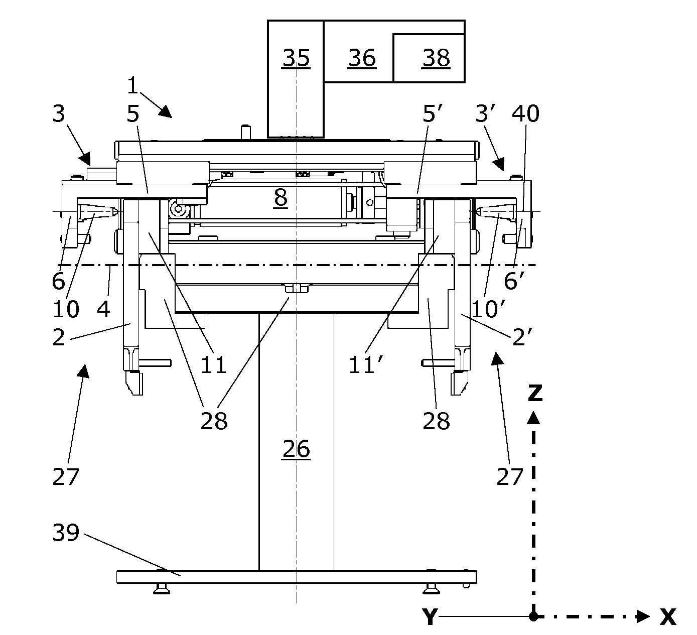
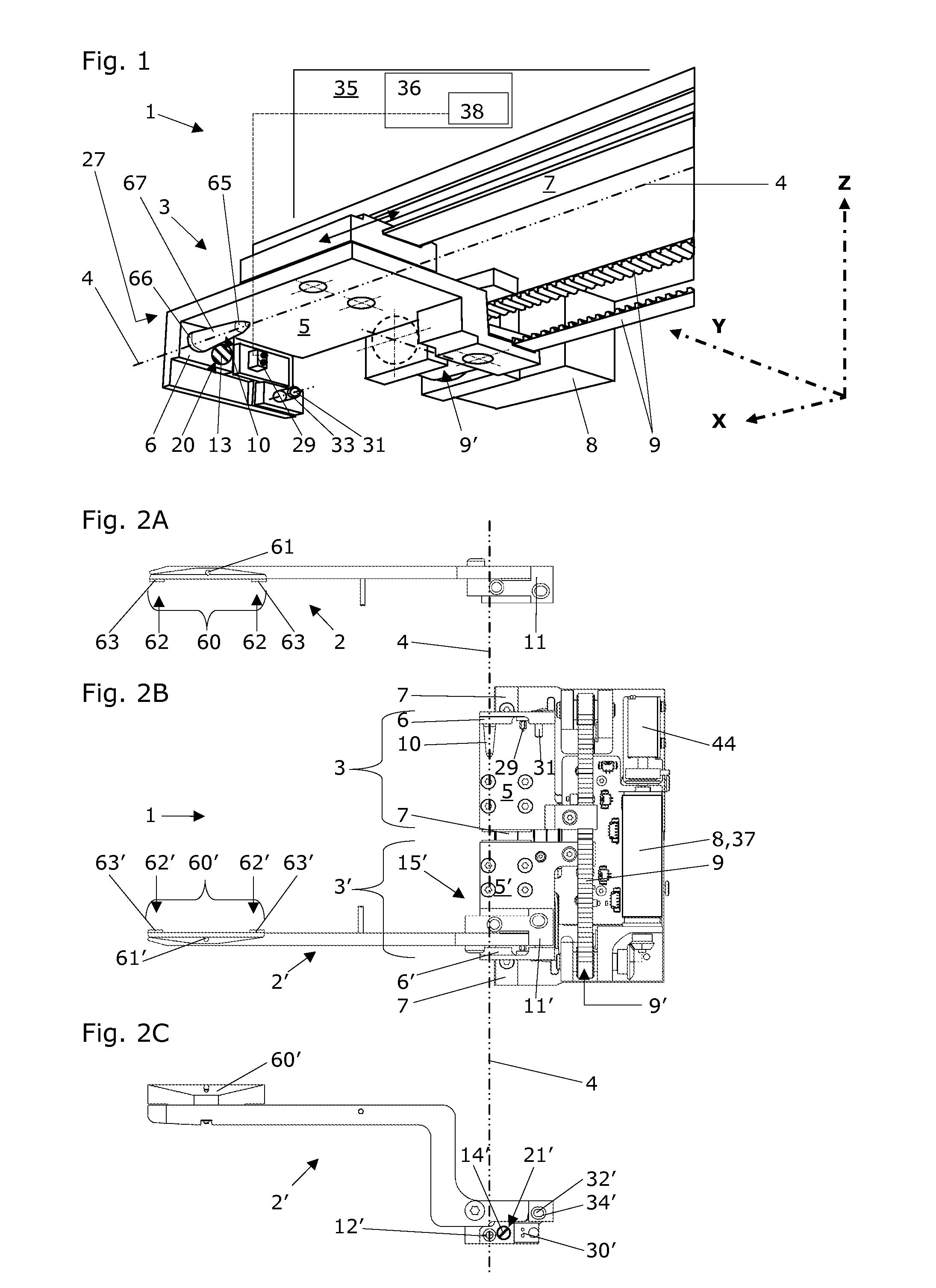
[0069]FIG. 1 shows a three-dimensional view of one of the two gripper jaws 3,3′ of a gripper claw 1 according to the invention having a lateral holding mandrel arrangement and the arrangement thereof in a three-dimensional coordinate system. The lateral fastening of the holding mandrels 10,10 is preferably selected so that the holding mandrels 10,10′ are arranged coaxially to a first axis 4. The first axis 4 extends parallel to the horizontal X axis of a Cartesian coordinate system.

[0070]A part of a gripper claw 1 is shown having replaceable gripper fingers 2,2′ (cf. FIG. 2) for grasping and depositing objects. This gripper claw 1 comprises two gripper jaws 3,3′, only one of which is shown here. The gripper jaws 3,3′ each comprise one first jaw flange 5,5′ parallel to the first axis 4. These two gripper jaws 3,3′ are fastened so they are movable using their respective first jaw flange 5,5′ on at least one linear guide 7 and are implemented as movable toward one another and away fro...

second embodiment

[0122]FIG. 9B shows the second embodiment having holding mandrels 10,10′ aligned parallel to one another and perpendicularly to the direction of the X axis or the first axis 4. The holding mandrels 10,10′ and the guide pins 31,31′ are preferably fastened using a press fit on the second jaw flanges 6,6′. The holding axis 40 is identical to the Y axis here.

[0123]In the middle, a part of a corresponding finger base 11′ having its complementary depression 12′ is shown, this complementary depression 12′ extending with its holding axis 40 in the direction of the Y axis or perpendicularly to the first axis 4. In addition, this finger base 11,11′ shown here has vertical holding seats 43,43′, only one of these holding seats being shown.

[0124]A part of a corresponding link 28 having two vertically protruding holding pins 42,42′ is shown at the bottom, which fit in a formfitting manner in the vertical holding seats 43,43′ of the respective finger base 11,11′.

[0125]The engagement of the holding...


PUM

PropertyMeasurementUnit
Fractionaaaaaaaaaa
Lengthaaaaaaaaaa
Diameteraaaaaaaaaa

Abstract

A gripper claw has replaceable gripper fingers and two gripper jaws each with a first jaw flange. The jaws are fastened to respective jaw flanges and are movable on linear guides, toward and away from one another. Each jaw has a holding mandrel, with holding cone. Each finger is reversibly insertable into one gripper jaw and has a finger base with depression complementary to a respective cone. The cone has a length that is at least one-third of its largest diameter, and its smallest diameter is at most 90% of the largest cone diameter. The jaws and the bases form a holding mechanism which holds the fingers in a stop position on a respective gripper jaw and they form a stabilizing mechanism that, with the holding cone, prevent tilting of the fingers.

Description

RELATED PATENT APPLICATIONS[0001]This patent application claims priority of the Swiss Patent Application No. 01218 / 11 filed on Jul. 21, 2011, the entire disclosure thereof is herein incorporated by explicit reference for any purpose.TECHNICAL FIELD OF THE INVENTION[0002]The invention relates to a gripper claw with gripper fingers insertable reversibly therein for grasping and depositing objects. In addition, the invention relates to a robot and methods for the robotic receiving and releasing of gripper fingers using such a gripper claw. Such gripper claws typically comprise two gripper jaws which carry the gripper fingers, and which are fastened so that they are movable on linear guides and are designed as movable toward one another and away from one another. The two gripper fingers attached thereon can thus also be moved exactly toward one another or away from one another, so that objects can be received and deposited again in a targeted manner. Such grippers are referred to as par...

Claims


Application Information

Patent Timeline
IPC IPC(8): B25J15/00B23P11/00B66C1/42
CPCY10T29/49815Y10T29/49826B25J15/0475B25J15/026
Inventor BIELER, TINO
Owner TECAN TRADING AG
Learn More