Appliance control system

a control system and control system technology, applied in the field of application control system, can solve the problems of user being required to perform such a troublesome procedure, and achieve the effect of reducing the amount of power consumption

Active Publication Date: 2013-01-24
PANASONIC INTELLECTUAL PROPERTY MANAGEMENT CO LTD
View PDF6 Cites 20 Cited by
  • Summary
  • Abstract
  • Description
  • Claims
  • Application Information

AI Technical Summary

Benefits of technology

[0008]In the third aspect of the appliance control system in accordance with the present invention, in addition to the second aspect, each of the electrical appliances includes a reduction measurement unit and an information creation unit. The reduction measurement unit is configured to measure a difference in the power consumption of the functional unit between a previous operation state and the current operation state. The previous operation state is defined as the operation state of the functional unit before performance of the energy conservation control process in response to receipt of the control instruction by the functional unit, and the current operation state is defined as the operation state of the functional unit after the performance of the energy conservation control process by the functional unit. The information creation unit is configured to create the individual control information regarding the previous operation state by associating the control instruction provided to the functional unit with the difference of the power consumption measured by the reduction measurement unit as the individual reduction amount.
[0009]In the fourth aspect of the appliance control system in accordance with the present invention, in addition to any one of the first to third aspects, the appliance control system further includes a time period storage unit and a time period judging unit. The energy conservation instruction further includes an energy conservation time period indicative of a continuous time period of the energy conservation control process. The time period storage unit is configured to store an allowed continuous time period for which the functional unit of the electrical appliance is allowed to continue the energy conservation control process corresponding to the common control order. The time period judging unit is configured to, upon receiving the energy conservation instruction, refer to the time period storage unit, and retrieve the allowed continuous time period associated with the energy conservation control process which is performed by the functional unit in accordance with the power conservation instruction, and prohibit the functional unit from performing the energy conservation control process upon acknowledging that the allowed continuous time period is equal to or less than the energy conservation time period included in the energy conservation instruction.
[0010]In the fifth aspect of the appliance control system in accordance with the present invention, in addition to any one of the first to fourth aspects, the appliance control device further includes a capability storage unit configured to store, for each electrical appliance, an energy conservation capability indicative of a decreased amount of power consumption caused by the performance of the energy conservation control process by the functional unit. The control unit is configured to, upon acknowledging that the external interface un

Problems solved by technology

Consequently, the user is required to

Method used


Image

  • Appliance control system
  • Appliance control system
  • Appliance control system

Examples


first embodiment

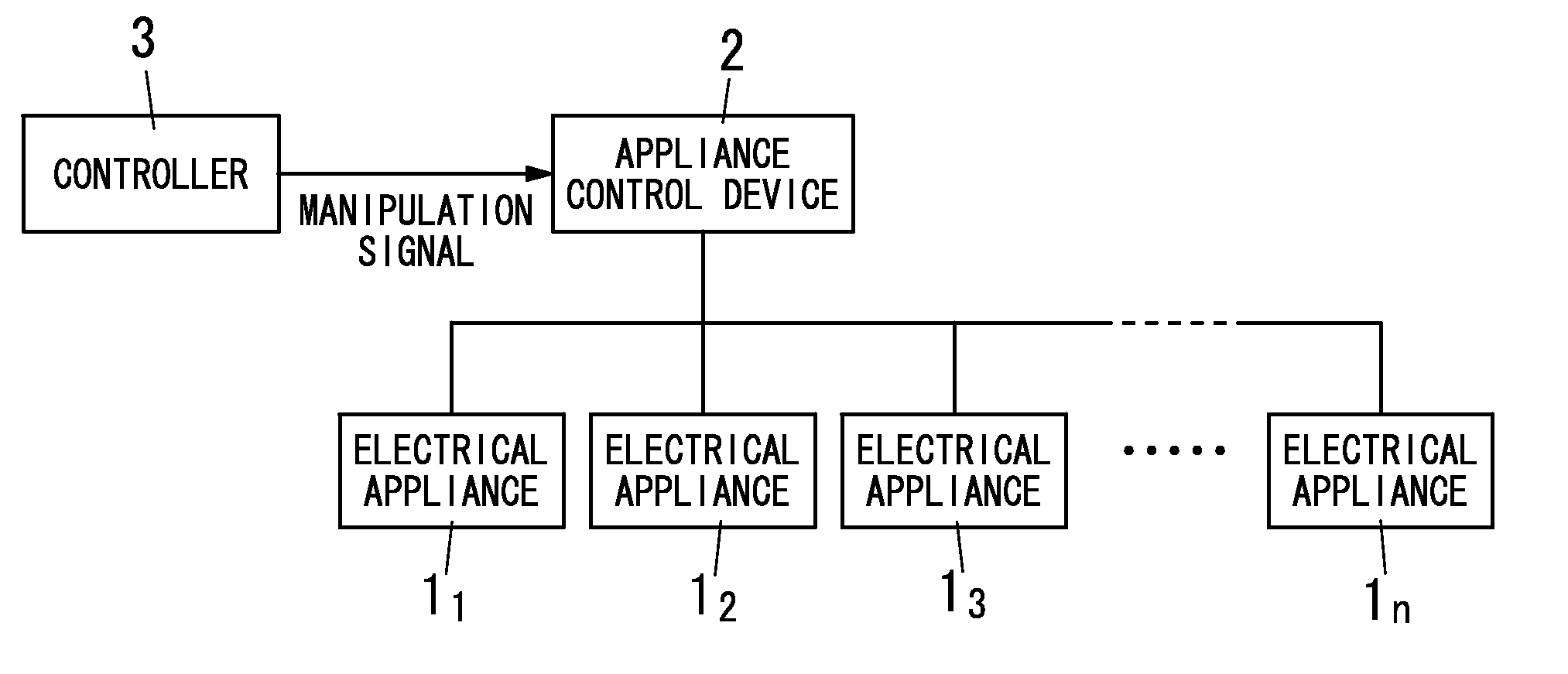
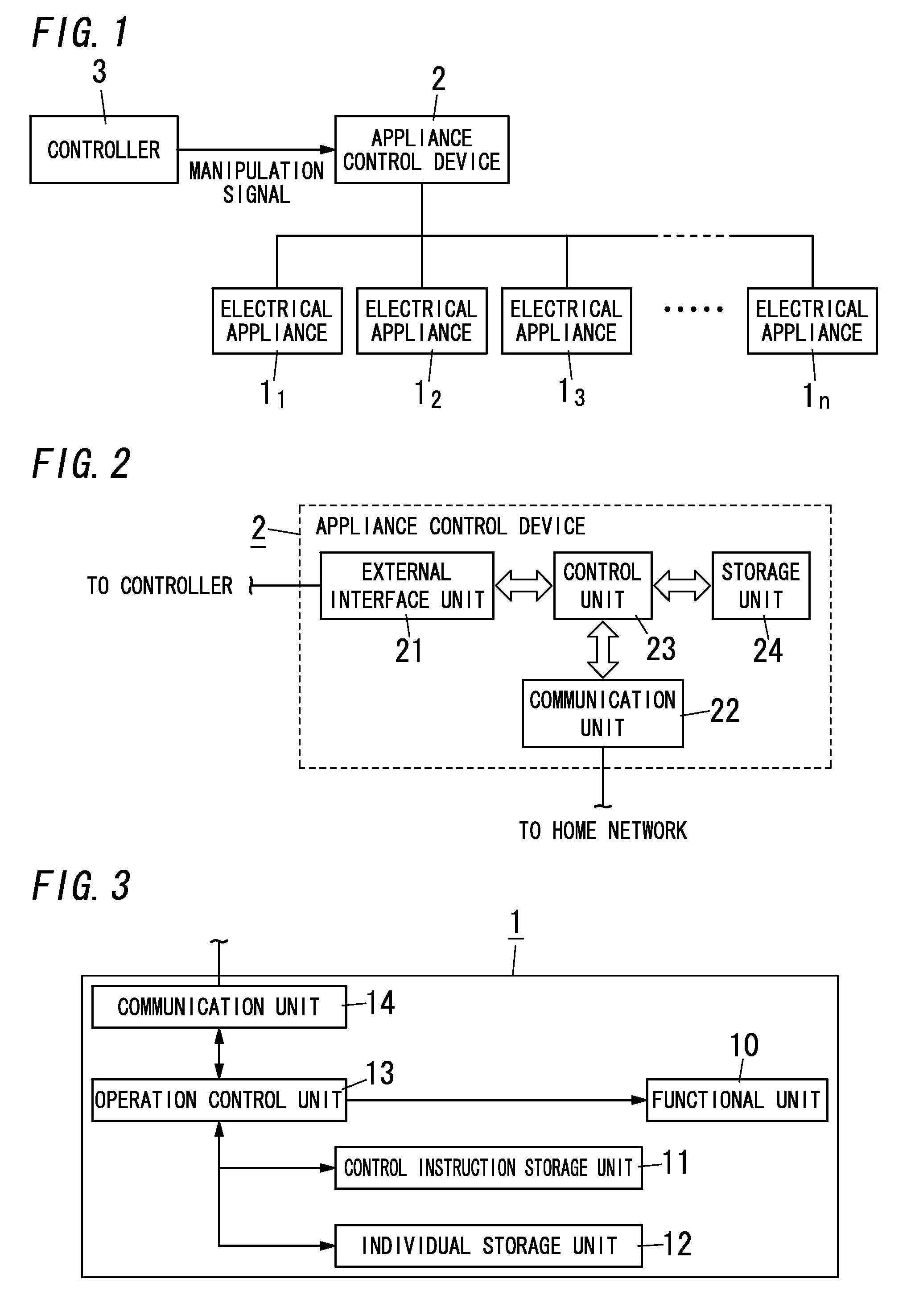
[0021]As shown in FIG. 1, the appliance control system of the present embodiment includes plural electrical appliances (control-target appliances) 11, 12, . . . , 1n (the reference numeral “1” is used when there is no need to distinguish the respective appliances), an appliance control device 2 connected to the respective electrical appliances 1, and a controller 3 connected to the appliance control device 2. In the following explanation, it is assumed that each of the electrical appliances 1, the appliance control device 2, and the controller 3 is installed in a residence. For example, the electrical appliance 1 is a home appliance such as a lighting fixture, an air conditioner, a refrigerator, and a washing machine. As mentioned in the above, the appliance control system includes the plural electrical appliances 1 configured to operate with electrical power supplied from an external power source (e.g., a commercial power source, and a DC power source such as a solar cell and a fue...

second embodiment

[0071]The appliance control system of the present embodiment is different from the appliance control system of the first embodiment in that the energy conservation instruction which is received by the appliance control device 2 from the controller 3 includes a parameter for defining a time period for the reduction of the power consumption. In brief, in the present embodiment, the energy conservation instruction includes the total reduction amount and an energy conservation time period indicative of a continuous time period of the energy conservation control process.

[0072]In other words, in the present embodiment, the energy conservation instruction indicates the reduction amount of the power consumption as electric energy. For example, the energy conservation instruction indicates reducing electrical power by 100 W for 2 hours (=200 Wh). Accordingly, a user can request the energy conservation control process by designating electrical energy by use of the controller 3. Consequently, ...

third embodiment

[0081]The appliance control system of the present embodiment is different from the appliance control system of the first embodiment in that the appliance control device 2 selects the control order performed by the electrical appliance 1 in consideration of an energy conservation capability of the electrical appliance 1.

[0082]In the appliance control device 2 of the present embodiment, the storage unit 24 is configured to store, for each electrical appliance 1, the energy conservation capability indicative of a decreased amount of the power consumption caused by the performance of the energy conservation control process by the functional unit 10. For example, as shown in following TABLE 3, the storage unit 24 stores the energy conservation capabilities (expressed in the unit of the percentage) of 10%, 20%, and 50% with regard to the electrical appliance 11. The energy conservation capability expressed in the unit of the percentage is calculated based on rated power consumption. The e...


PUM


Abstract

The appliance control system includes electrical appliances and an appliance control device. The appliance control device includes a control unit configured to, upon receiving an energy conservation instruction indicative of a total reduction amount, send a control signal including common control order indicative of an individual reduction amount of the power consumption of the electrical appliance to at least one of the electrical appliances based on the total reduction amount. Each electrical appliance includes a functional unit having plural operation states with different power consumption, a control instruction storage unit storing plural control instructions for changing the operation state, an individual storage unit storing individual control information indicative of a correspondence relation between the individual reduction amount and the control instruction, and an operation control unit. Upon receiving the control signal, the operation control unit selects the control instruction associated with the individual reduction amount indicated by the common control order included in the received control signal with reference to the individual control information, and provides the selected control instruction to the functional unit. The functional unit performs an energy conservation control process of changing the operation state in accordance with the received control instruction.

Description

TECHNICAL FIELD[0001]The present invention relates to an appliance control system which can reduce power consumption of electrical appliances (control-target appliances) to achieve energy conservation.BACKGROUND ART[0002]With the increased concern for energy conservation in recent years, general consumer's awareness of energy conservation has been raised. For example, general consumers prefer to buy electrical appliances with low power consumption. There has been proposed an appliance control system (cf., JP 2006-332974 A). The appliance control system performs centralized control of plural electrical appliances installed in a residence. The appliance control system reduces total power consumption of the electrical appliances in the residence. Hence, the appliance control system can conserve energy.[0003]However, in such a residence, various types of electrical appliances such as a lighting fixture, an air conditioner, and a refrigerator are installed. Hence, to reduce power consump...

Claims


Application Information

Patent Timeline
IPC IPC(8): H02J4/00
CPCH02J3/14Y02B70/3225H02J2003/143Y02B70/3266Y04S20/242Y04S20/222H02J2310/14Y02B70/30
Inventor TAKEHARA, KIYOTAKAYANAGI, YASUHIRO
Owner PANASONIC INTELLECTUAL PROPERTY MANAGEMENT CO LTD
Why Eureka
Try Eureka