Apparatus for detecting end of strip and method of doing the same

a technology of end strips and antennae, which is applied in the field of antennae for detecting end strips and the same, can solve the problems of camera preparation, error in detecting the location of the end strips, etc., and achieve the effect of accurate detection of the location of the opposite end

Inactive Publication Date: 2013-01-24
NIRECO CORP
View PDF6 Cites 11 Cited by
  • Summary
  • Abstract
  • Description
  • Claims
  • Application Information

AI Technical Summary

Benefits of technology

[0067]The apparatus for detecting an end of a strip in width-wise and height-wise directions and the method of doing the same, both in accordance with the present invention, make it possible to accurately detect locations of opposite ends of a running strip in a width-wise directions without including an additional element such as the half mirror 1302 unlike the conventional apparatus 1000 illustrated in FIG. 16, and further without being influenced by partial upward and downward motion of a strip.
[0068]Furthermore, the apparatus for detecting an end of a strip in width-wise and height-wise directions and the method of doing the same, both in accordance with the present invention, make it possible to detect a height of opposite ends of a strip (a height relative to a reference height), if a running strip partially rises.

Problems solved by technology

Since a camera taking a photograph of a strip is arranged on the assumption that a strip runs at a constant height, if a strip partially vertically moves, locations of opposite ends of a strip would vary in a field of view of the camera, and resultingly, there would be caused an error in detecting locations of the ends.
However, the apparatus is accompanied with a structural problem that two cameras have to be prepared for each of ends.

Method used


Image

  • Apparatus for detecting end of strip and method of doing the same
  • Apparatus for detecting end of strip and method of doing the same
  • Apparatus for detecting end of strip and method of doing the same

Examples


first embodiment

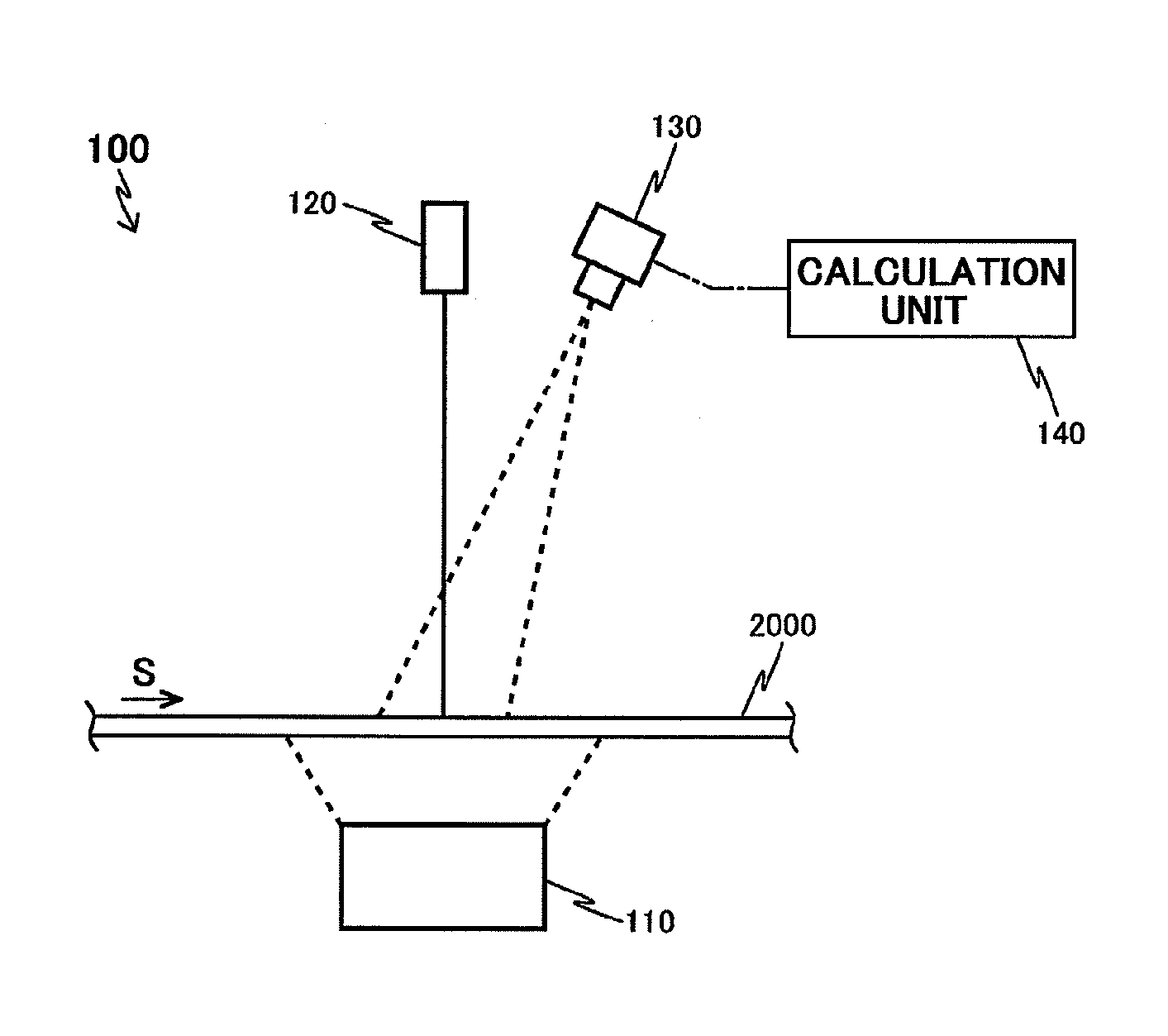
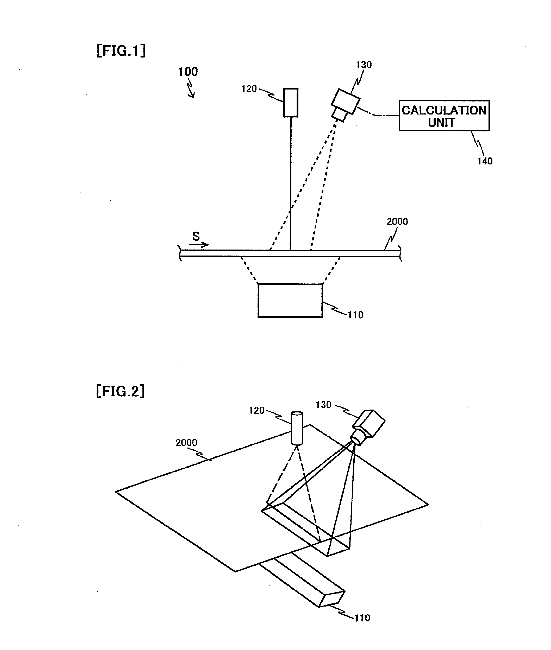
[0086]FIG. 1 illustrates a structure of the apparatus 100 for detecting an end of a strip in width-wise and height-wise directions, in accordance with the first embodiment of the present invention.

[0087]The apparatus 100 in accordance with the first embodiment detects opposite ends of a strip 2000 in a width-wise direction (opposite ends in a direction perpendicular to a plane defined by FIG. 1), running in a direction S towards right in FIG. 1, and further, a height (a location in a height-wise direction) of the ends.

[0088]The strip 2000 is not always running at a constant height, but is sometimes partially rising or waving. That is, the strip 2000 sometimes partially moves vertically while running.

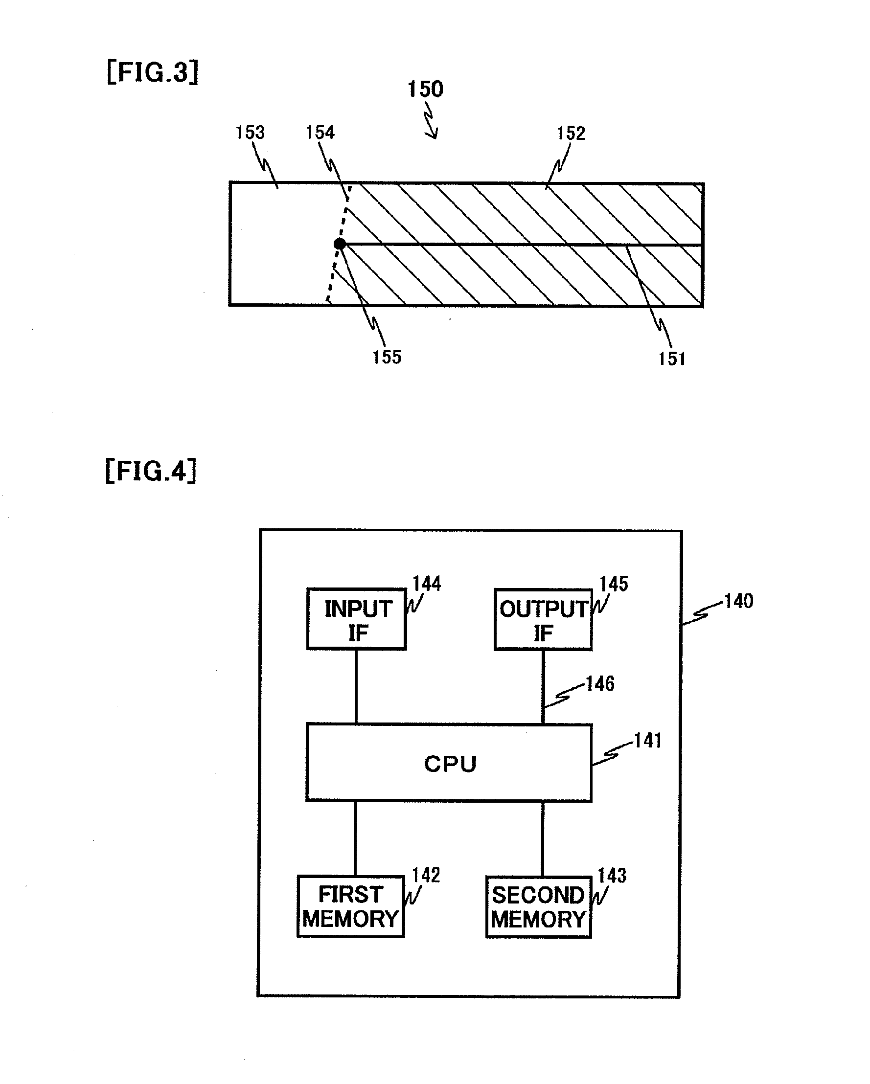
[0089]The apparatus 100 in accordance with the first embodiment includes a first light-source 110 irradiating a light onto a lower surface of the strip 2000, a second light-source 120 irradiating a linear light onto an upper surface of the strip 2000, a camera 130, and a calculation unit...

second embodiment

[0160]FIG. 13 illustrates a structure of the apparatus 200 for detecting an end of a strip, in accordance with the second embodiment of the present invention.

[0161]The apparatus 200 in accordance with the second embodiment is designed to include a first light-source 210 in place of the first light-source 110 in comparison with the apparatus 100 in accordance with the first embodiment. The apparatus 200 in accordance with the second embodiment has the same structure as that of the apparatus 100 in accordance with the first embodiment except including the first light-source 210 in place of the first light-source 110. Accordingly, parts or elements that correspond to those of the first embodiment have been provided with the same reference numerals.

[0162]The first light-source 210 is situated above the strip 2000, and irradiates a light onto a surface of the strip 2000 around the linear beam irradiated from the second light-source 120.

[0163]Furthermore, the second light-source 120 is de...

third embodiment

[0185]FIG. 15 illustrates a structure of the apparatus 300 for detecting an end of a strip, in accordance with the third embodiment of the present invention.

[0186]The apparatus 300 in accordance with the third embodiment is structurally different from the apparatuses 100 and 200 in accordance with the first and second embodiments in that whereas the apparatuses 100 and 200 are used for the strip 2000 which does not irradiate a light itself, the apparatus 300 is used for a strip 2001 which irradiate a light itself.

[0187]Accordingly, the apparatus 300 in accordance with the third embodiment is structurally different from the apparatus 100 in accordance with the first embodiment only in not including the first light-source 110.

[0188]In the apparatus 300 in accordance with the third embodiment, a light 2002 irradiated from the strip 2001 is used instead of a light irradiated from the first light-source 110. Thus, the apparatus 300 in accordance with the third embodiment can provide the ...


PUM


Abstract

The apparatus in accordance with the present invention detects locations of opposite ends of a running strip in a width-wise direction and heights of the ends. The apparatus includes a first light-source irradiating a light onto a lower surface of a strip, a second light-source perpendicularly irradiating a linear light onto an upper surface of the strip, a camera taking a photo of the strip, and a calculation unit calculating locations of opposite ends of the strip in width-wise and height-wise directions thereof, based on an image resulted from a light irradiated from the first light-source and an image resulted from a light irradiated from the second light-source and reflected at the strip.

Description

FIELD OF THE INVENTION[0001]The invention relates to an apparatus and a method for detecting an end of a strip in width-wise and height-wise directions while the strip is running in a direction with vertical motion.BACKGROUND ART[0002]An inspection as to whether patterns are accurately printed onto a surface of a strip (for instance, a sheet such as a film) is carried out, for instance, by causing the strip to run in a direction, taking a photo of the patterns of the strip, and analyzing photographs of the patterns (for instance, by comparing the patterns to reference patterns). Since it is necessary in the inspection to detect opposite ends of the running strip, a photo-taking device such as a camera was situated above the strip, a photo of the strip was taken by means of the photo-taking device, and opposite ends of the strip were detected in the taken photograph, in a conventional system.[0003]A strip is not always running at a constant height, but is sometimes partially rising o...

Claims


Application Information

Patent Timeline
Patent Type & Authority Applications(United States)
IPC IPC(8): H04N7/18
CPCG01B11/04G01B11/028G01B11/00
Inventor IWASE, HIROHIKOKON, YOSHIAKIKUBOTA, TOSHIHARU
Owner NIRECO CORP
Why Eureka
Try Eureka