Electromagnetic actuator with function detecting position of driven member

a technology of electromagnetic actuator and drive member, which is applied in the direction of relays, electronic commutators, instruments, etc., can solve the problems of inconvenient electromagnetic actuator type, low detection sensitivity of this type, and restricted design freedom of electromagnetic actuator driving mechanism, etc., and achieves the effect of convenient adjustmen

Inactive Publication Date: 2002-08-20
MIKUNI CORP
View PDF8 Cites 8 Cited by
  • Summary
  • Abstract
  • Description
  • Claims
  • Application Information

AI Technical Summary

Benefits of technology

The present invention has been made to solve such problems mentioned above and to provide an electromagnetic actuator which can detect precisely the location of the driven member by detecting the density of magnetic flux where the density is high. The driving mechanism does not need the design change

Problems solved by technology

However, this type of electromagnetic actuator has such an inconvenience that the detection sensitivity of this type remains low because the Hall sensor 8 detecting the rotation angle of rotor 6 is located in the magnetic field formed by the magnetic flux distributed by the magnetic coil 3, and the density of magnetic flux passing through the Hall sensor is low.
Moreover, there is another inconvenience that, freedom in design of a driving mechanism in the electromagnetic actuator is restricted in order to spare some space f

Method used


Image

  • Electromagnetic actuator with function detecting position of driven member
  • Electromagnetic actuator with function detecting position of driven member
  • Electromagnetic actuator with function detecting position of driven member

Examples


first embodiment

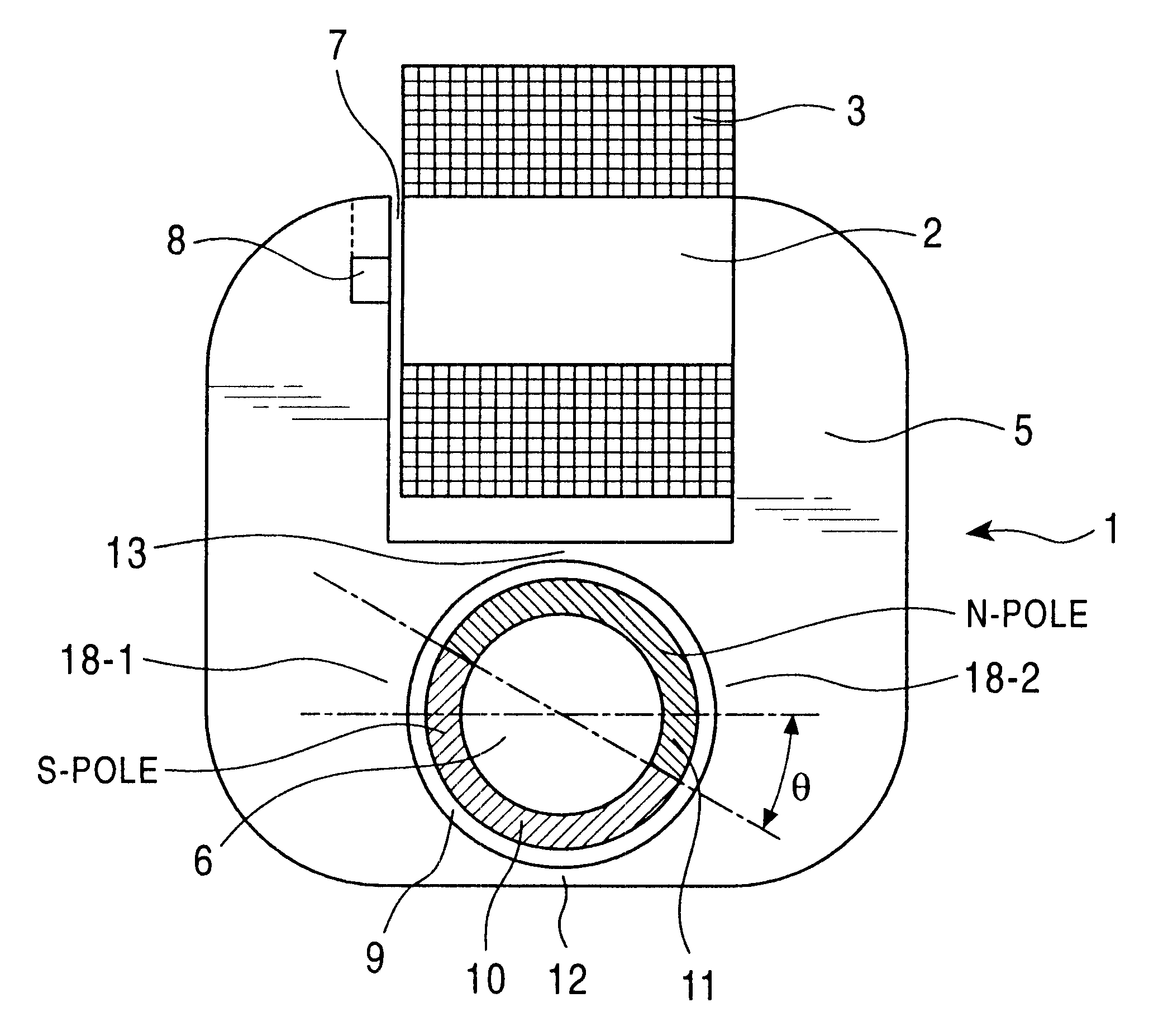
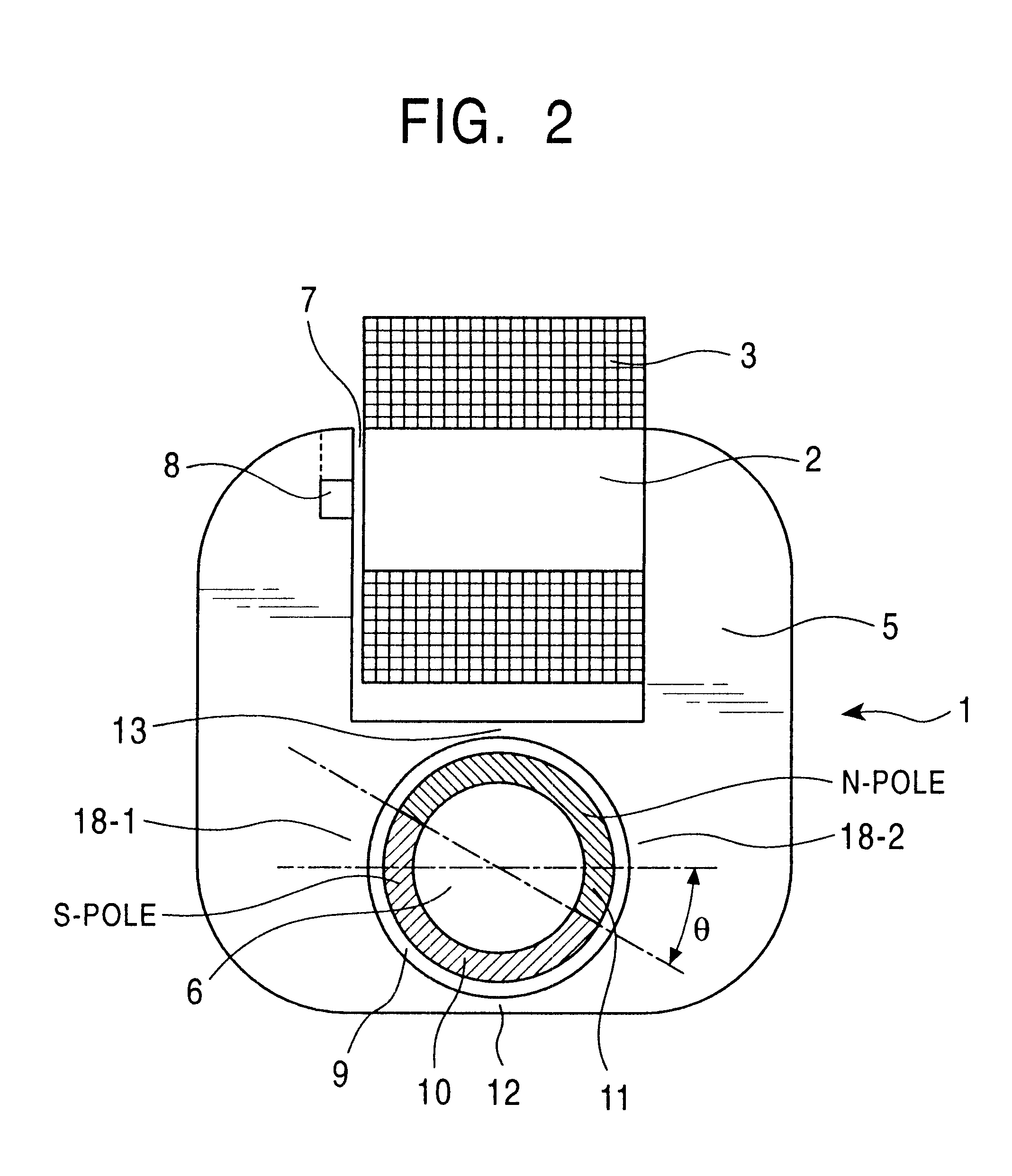
FIG. 2 shows an electromagnetic actuator as the present invention.

A core section 2 which is a magnetic flux formation section of the electromagnetic actuator 1 is provided with an electromagnetic coil 3 wound therearound. The electromagnetic coil 3 is connected to a power source (not shown) and a current from the power source is supplied to the electromagnetic coil 3. To one end of the core section 2, an electromagnetic component yoke 5 is connected, and the other end of the core section 2 faces toward the yoke 5 via a magnetic gap 7. Within the yoke 5 is formed an opening 9 within which a rotor 6 i.e. movable member is provided without touching the inside wall of opening 9 while facing magnetic pieces of 18-1 and 18-2. The rotor 6 is made of a magnetic material. The surface of the rotor 6 is magnetized so as to produce different poles, for example such permanent magnets 10 and 11. Permanent magnets 10 and 11 are magnetized in the opposite directions. For example the permanents magn...


PUM


Abstract

An electromagnetic actuator can precisely detect the position of a driven member by detecting a magnetic flux density at a portion where the magnetic flux is condensed. The electromagnetic actuator comprises magnetic flux density detecting means disposed in a gap formed within a magnet flux formation section that is wound by an electromagnetic coil, for detecting a magnetic flux density within the gap; current value detecting means for detecting a current flowing through the electromagnetic coil; and calculating means for calculating a position of a movable member on the basis of the magnetic flux density detected by the magnetic flux density detection means and the current value detected by the current detection means.

Description

1. Field of the InventionThe present invention relates to an electromagnetic actuator and, in particular, especially to an electromagnetic actuator which can drive a driven member while detecting a position of the driven member.2. Description of Related ArtAn electromagnetic actuator which drives a driven member has needed a position sensor for detecting an actual position of the driven member which sensor is separate from the electromagnetic actuator itself. To solve this problem, as well as to make the costs lower and to save space, the applicant proposed such an electromagnetic actuator which involves a movable member as a driven member being driven while detecting the actual position of the movable member in Japanese Patent Kokai 8-275460. The outline of this apparatus is as shown in FIG. 1. In FIG. 1, an electromagnetic coil 3 is wound around a yoke 5. A pair of magnetic poles 101 and 102 of the yoke 5 are located to face each other via an air gap to distribute a magnetic flux ...

Claims


Application Information

Patent Timeline
IPC IPC(8): H02K26/00H02K11/00H02P6/16H02P6/14G01B7/30G01B7/00H02K33/16
CPCH02K11/0015H02K11/0021H02K26/00H02P6/16H02K11/21H02K11/215H02K11/00
Inventor MURAJI, TETSUO
Owner MIKUNI CORP
Why Eureka
Try Eureka