Microwave and RF ablation system and related method for dynamic impedance matching

a dynamic impedance matching and ablation system technology, applied in the field of medical procedures, can solve the problems of unbalanced transmission lines, unbalanced transmission lines, and unbalanced transmission lines, and achieve the effect of compact siz

Active Publication Date: 2013-01-24
TYCO HEALTHCARE GRP LP
View PDF10 Cites 36 Cited by
  • Summary
  • Abstract
  • Description
  • Claims
  • Application Information

AI Technical Summary

Problems solved by technology

Generally, the transmission line employed may have losses associated therewith that may be attributable to many factors.
The ratio of the forward (primary) wave amplitude to the reflected wave amplitude is expressed as a reflection coefficient F. Standing waves within the transmission line may result from constructive and destructive interference between forward and reflected waves.
As an example, an unbalanced transmission line may exhibit an undesirably large VSWR up to around 4:1.
Standing waves created within the transmission line can contribute to the power loss associated with impedance mismatch, cause inaccurate energy dose (i.e., power) measurements, and impair monitoring of parameters associated with the surgical procedure.
Moreover, standing waves may cause localized heating and failure of an interconnect (i.e., cable or coaxial cable), and cause premature wear and / or failure of the microwave or RF generator.
Conventional impedance matching circuits may include devices such as motor-driven variable reactive elements, i.e., vacuum variable capacitors, and as a result may be large in size.
In addition, because the energy source may have a much smaller wavelength than the length of the transmission line, it is often difficult to achieve accurate impedance matching in a rugged, reliable, and relatively compact design.

Method used


Image

  • Microwave and RF ablation system and related method for dynamic impedance matching
  • Microwave and RF ablation system and related method for dynamic impedance matching
  • Microwave and RF ablation system and related method for dynamic impedance matching

Examples


Embodiment Construction

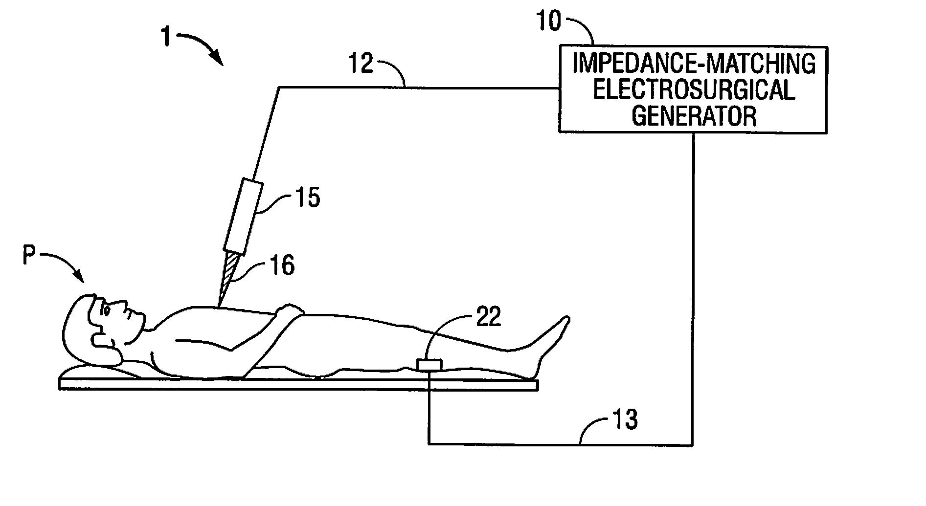
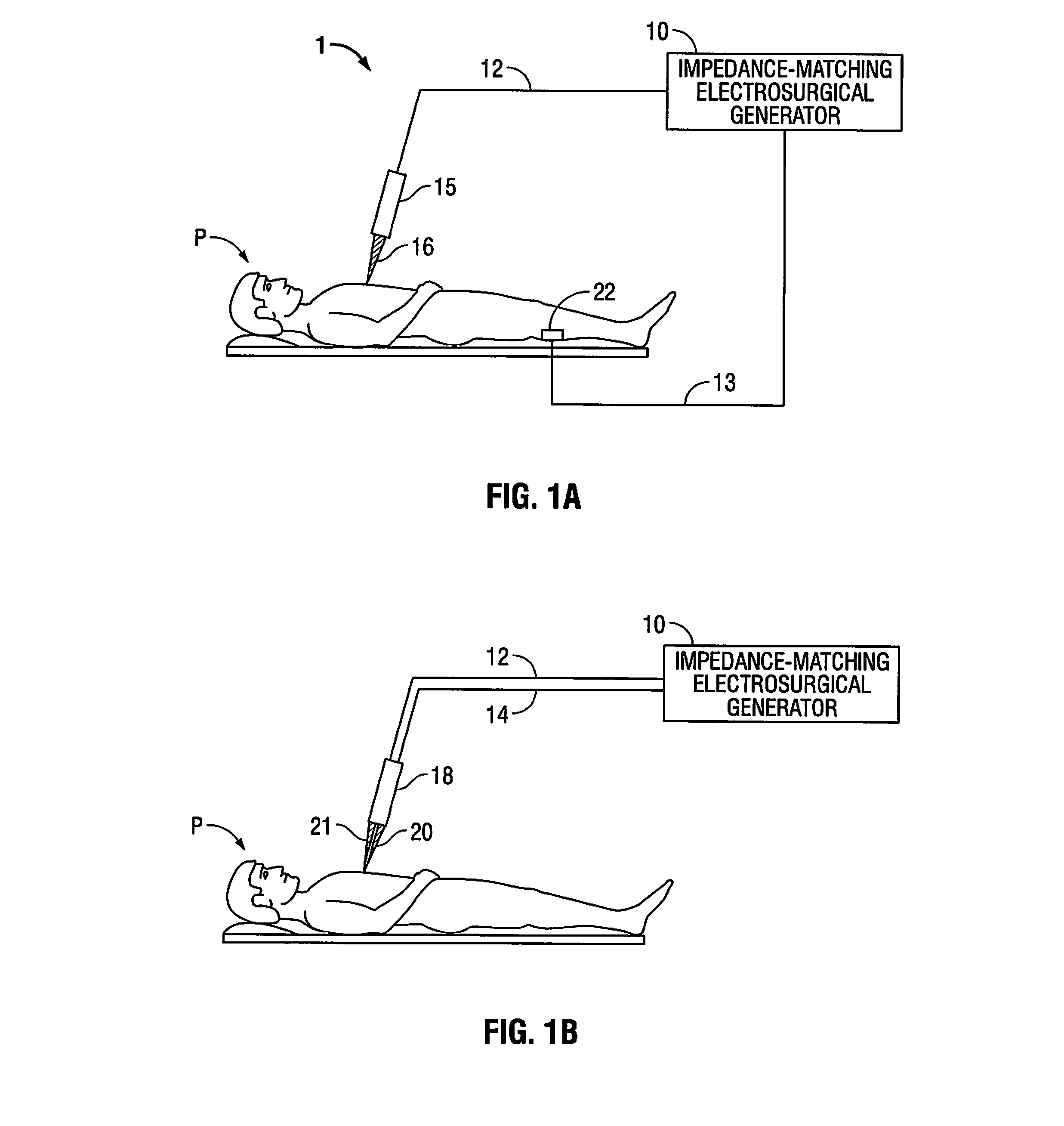
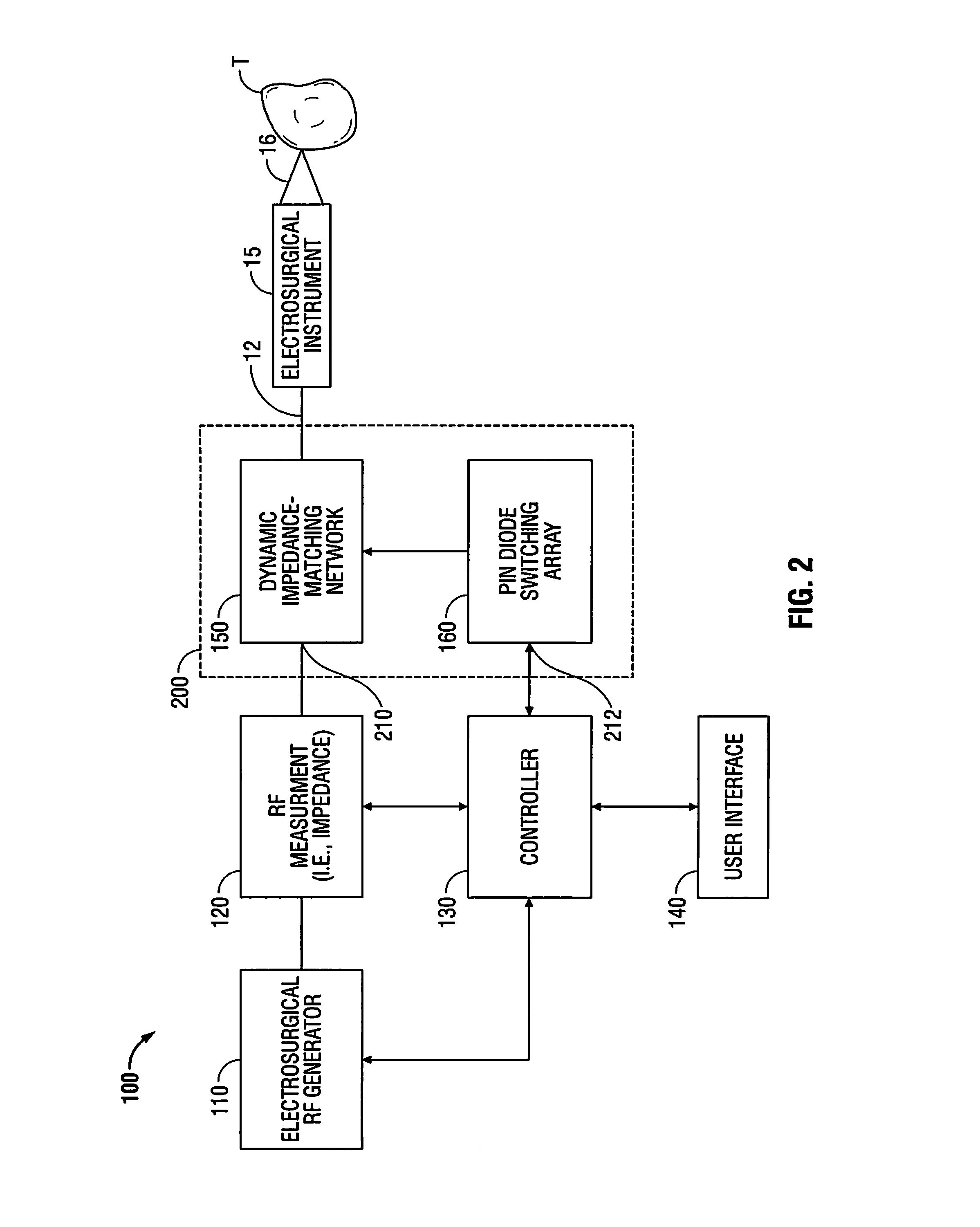
[0028]Particular embodiments of the present disclosure will be described hereinbelow with reference to the accompanying drawings. In the following description, well-known functions or constructions are not described in detail to avoid obscuring the present disclosure in unnecessary detail. Those skilled in the art will understand that the present disclosure may be adapted for use with either an endoscopic instrument, laparoscopic instrument, or an open instrument. It should also be appreciated that different electrical and mechanical connections and other considerations may apply to each particular type of instrument, however, the novel aspects with respect to electrosurgical impedance matching are generally consistent with respect to both the open or endoscopic designs.

[0029]In the drawings and in the description which follows, the term “proximal” refers to the end of the instrument which is closer to the user (i.e., further from the patient), while the term “distal” refers to the ...


PUM


Abstract

An electrosurgical system and method for performing electrosurgery is disclosed. The electrosurgical system includes an electrosurgical generator adapted to supply electrosurgical energy to tissue. The electrosurgical system includes an electrosurgical instrument, such as an electrosurgical antenna, knife, forceps, suction coagulator, or vessel sealer. The disclosed system includes an impedance sensor, a controller, dynamic impedance matching network, and an electrosurgical energy generator. The dynamic impedance matching network includes a PIN diode switching array configured to selectively activate a plurality of reactive elements. The disclosed arrangement of reactive elements provides real-time impedance correction over a wide range of impedance mismatch conditions.

Description

BACKGROUND[0001]1. Technical Field[0002]The present invention relates to systems and methods for performing a medical procedure, wherein the medical procedure includes transferring energy from an energy source to a patient via a transmission line and, more particularly, dynamically matching energy source impedance to tissue impedance.[0003]2. Background of Related Art[0004]Historically, surgery was performed using only mechanical tools, such as mechanical cutting instruments, scalpels, bladed forceps, saws, rongeurs, and the like. However, in recent years, technology has improved such that surgeons now frequently use electromagnetic waves to render a wider variety of surgical effects, e.g., by selectively modifying tissue using electromagnetic energy to produce a specific effect. The characteristics of the electromagnetic energy applied to tissue strongly correlates to the effect that the energy has on the tissue. These characteristics are therefore changed in accordance with the de...

Claims


Application Information

Patent Timeline
Patent Type & Authority Applications(United States)
IPC IPC(8): A61B18/12
CPCA61B18/1233A61B18/1477A61B2018/00577A61B2018/00589A61B2018/00595A61B2018/167A61B2018/00708A61B2018/00875A61B2018/141A61B2018/1412A61B2018/0063
Inventor COLLINS, GEORGE J.
Owner TYCO HEALTHCARE GRP LP
Why Eureka
Try Eureka