
Resonator device for damping the pressure oscillation within a combustion chamber and a method for operating a combustion arrangement

a technology of pressure oscillation and resonance device, which is applied in the direction of mechanical equipment, machines/engines, lighting and heating apparatus, etc., can solve the problems of adversely affecting the operation of the combustion chamber, the efficiency of the gas turbine, and the inability of the combustion chamber to work satisfactorily under changing running conditions, etc., to achieve the effect of rapid load change of the combustion chamber

Inactive Publication Date: 2013-01-31
SIEMENS AG
View PDF6 Cites 6 Cited by
  • Summary
  • Abstract
  • Description
  • Claims
  • Application Information

AI Technical Summary

Benefits of technology

The patent describes a combustion arrangement that uses a resonator device to damp pressure oscillations in a combustion chamber. The heating element in the container generates a flame that convects to create a uniform temperature distribution. This allows the resonator device to quickly change its resonance frequency to match the temperature of the gas inside the container, regardless of the load condition of the combustion chamber. This means that the resonator device can effectively damp pressure oscillations even when the combustion chamber is running under different conditions. The method also involves controlling the heating element to change the temperature of the gas in the container when the combustion chamber is operated in a different load condition, ensuring that the resonator device can effectively damp pressure oscillations even under changing load conditions. The high heating power and high temperature of the flame make plasma assisted combustion a suitable technology for damping pressure oscillations in a combustion chamber.

Problems solved by technology

These pressure oscillations adversely affect the operation of the combustion chamber, in particular the efficiency of the gas turbine comprising the combustion chamber.
It has been observed that a combustion chamber may not work satisfactorily under changing running conditions.

Method used


Image

  • Resonator device for damping the pressure oscillation within a combustion chamber and a method for operating a combustion arrangement
  • Resonator device for damping the pressure oscillation within a combustion chamber and a method for operating a combustion arrangement
  • Resonator device for damping the pressure oscillation within a combustion chamber and a method for operating a combustion arrangement

Examples


Embodiment Construction

[0039]The illustration in the drawing is schematically. It is noted that in different figures, similar or identical elements are provided with the same reference signs or with reference signs, which are different from the corresponding reference signs only within the first digit.

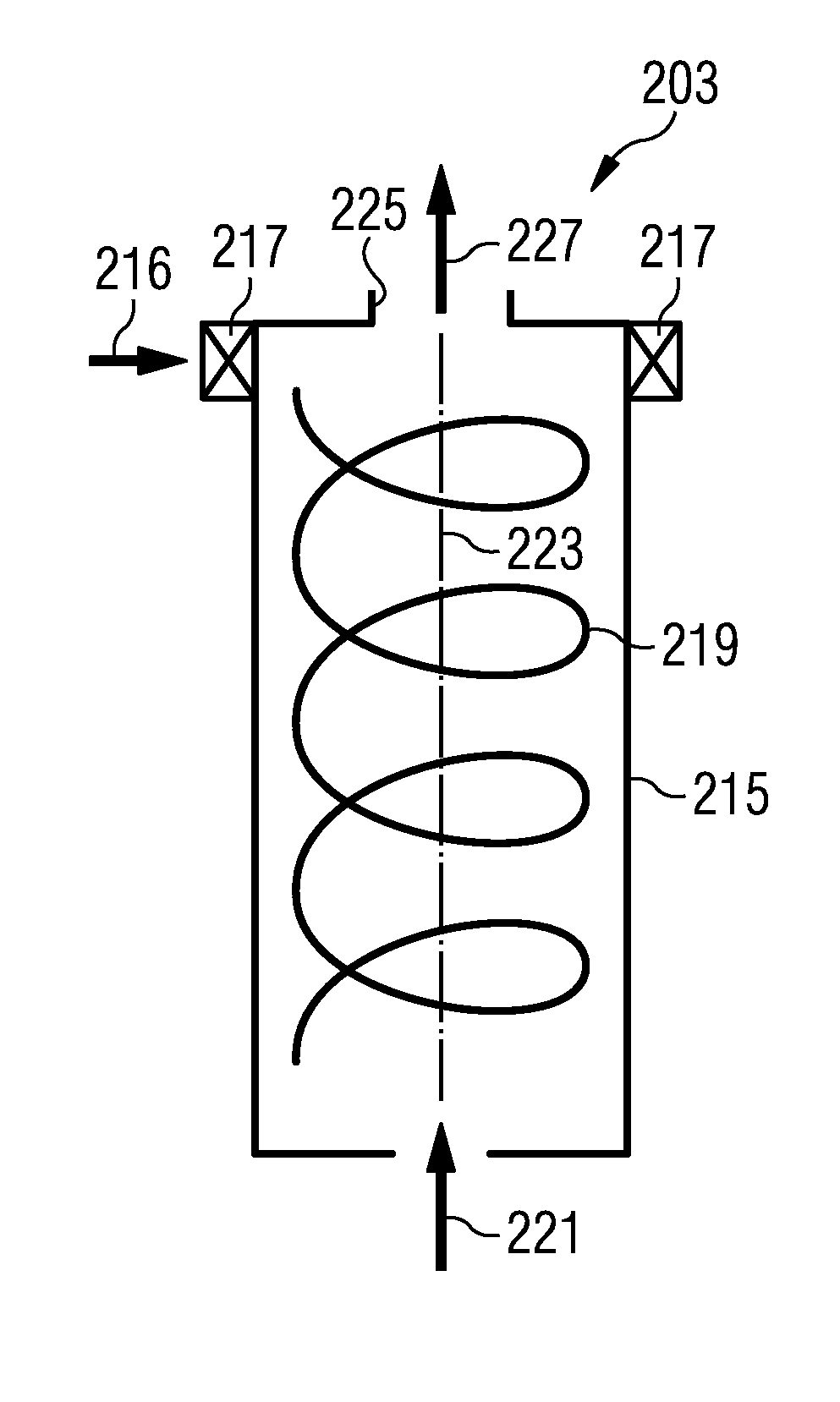
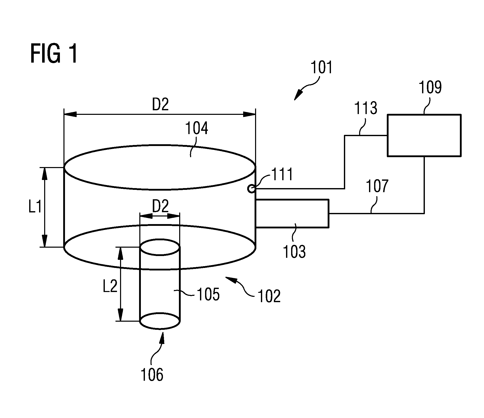
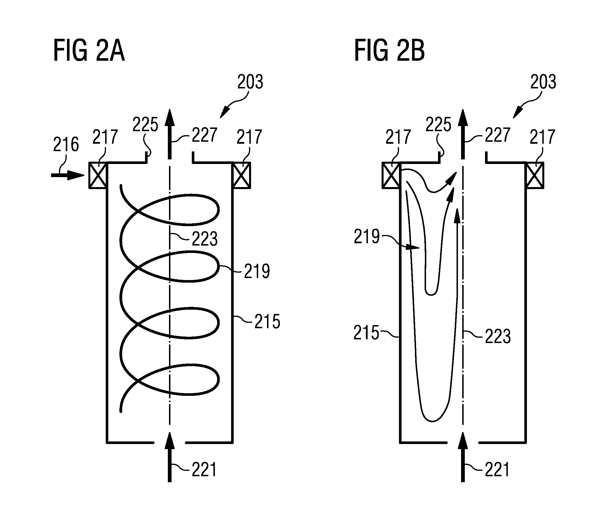
[0040]FIG. 1 schematically shows a resonator device 101 for damping a pressure oscillation within a combustion chamber. The resonator device 101 comprises a container 102 which is filled with a gas, such as air, and comprises a heating element 103 which is adapted as a reverse vortex plasma generator. The container 102 of the resonator device comprises a body portion 104 and a neck portion 105. The body portion 104 comprises a cylindrical container which is in communication with the neck portion 105 which also has a cylindrical shape but having a much smaller diameter D2 compared to the diameter D1 of the body portion 4 of the resonator device 101. The body portion has a length L1 and the neck portion has a ...


PUM


Abstract

A resonator device for damping a pressure oscillation within a combustion chamber is proposed. The resonator device has a container filled with a gas, an opening in the container and a heating element adapted to generate a flame. The flame is arranged to heat the gas within the container. The resonator device is in a combustion arrangement having a combustion chamber for defining a combustion space for burning fuel. The container is connected to the combustion chamber such that an inside of the container is in communication with the combustion space via the opening. The resonator device has a resonance frequency equal to a pressure oscillation frequency within the combustion chamber under normal load conditions.

Description

CROSS REFERENCE TO RELATED APPLICATIONS[0001]This application is the US National Stage of International Application No. PCT / EP2011 / 053426 filed Mar. 8, 2011 and claims the benefit thereof. The International Application claims the benefits of European application No. 10159747.4 filed Apr. 13, 2010, both of the applications are incorporated by reference herein in their entirety.FIELD OF THE INVENTION[0002]The present invention relates to a resonator device for damping the pressure oscillation within a combustion chamber and to a method for operating a combustion arrangement. In particular, the present invention relates to a resonator device for damping a pressure oscillation within a combustion chamber which can be adjusted to damp an oscillation having a frequency which is changed upon changing the running condition of the combustion chamber. Further, the present invention relates to a method of operating a combustion arrangement involving damping of a pressure oscillation within the...

Claims


Application Information

Patent Timeline
Patent Type & Authority Applications(United States)
IPC IPC(8): F02C7/24
CPCF23R3/002F23M20/005F23R2900/00013F02C7/24F05D2260/963F23R2900/00014
Inventor BULAT, GHENADIE
Owner SIEMENS AG
Learn More