Rotor of an electric machine with embedded permanent magnets and electric machine

Active Publication Date: 2013-01-31
VOLVO LASTVAGNAR AB
View PDF8 Cites 20 Cited by
  • Summary
  • Abstract
  • Description
  • Claims
  • Application Information

AI Technical Summary

Benefits of technology

[0037]The retainer element can be easily arranged and shaped to its desired application in the electric machine. Such a design for an internal or external rotor refers to radial flux machines. The machine can also be designed as axial flux or linear machine. In case of multiple layers of embedded permanent ma

Problems solved by technology

These bridges can be placed at the air gap or in between the magnets allowing the roto

Method used


Image

  • Rotor of an electric machine with embedded permanent magnets and electric machine
  • Rotor of an electric machine with embedded permanent magnets and electric machine
  • Rotor of an electric machine with embedded permanent magnets and electric machine

Examples


first embodiment

[0114]FIGS. 13a-13c illustrate a rotor 240 for an axial flux machine 200 similar to the one shown in FIG. 12, as front view (FIG. 13a), as cut view along line 13b-13b (FIG. 13b) and as side view (FIG. 3c).

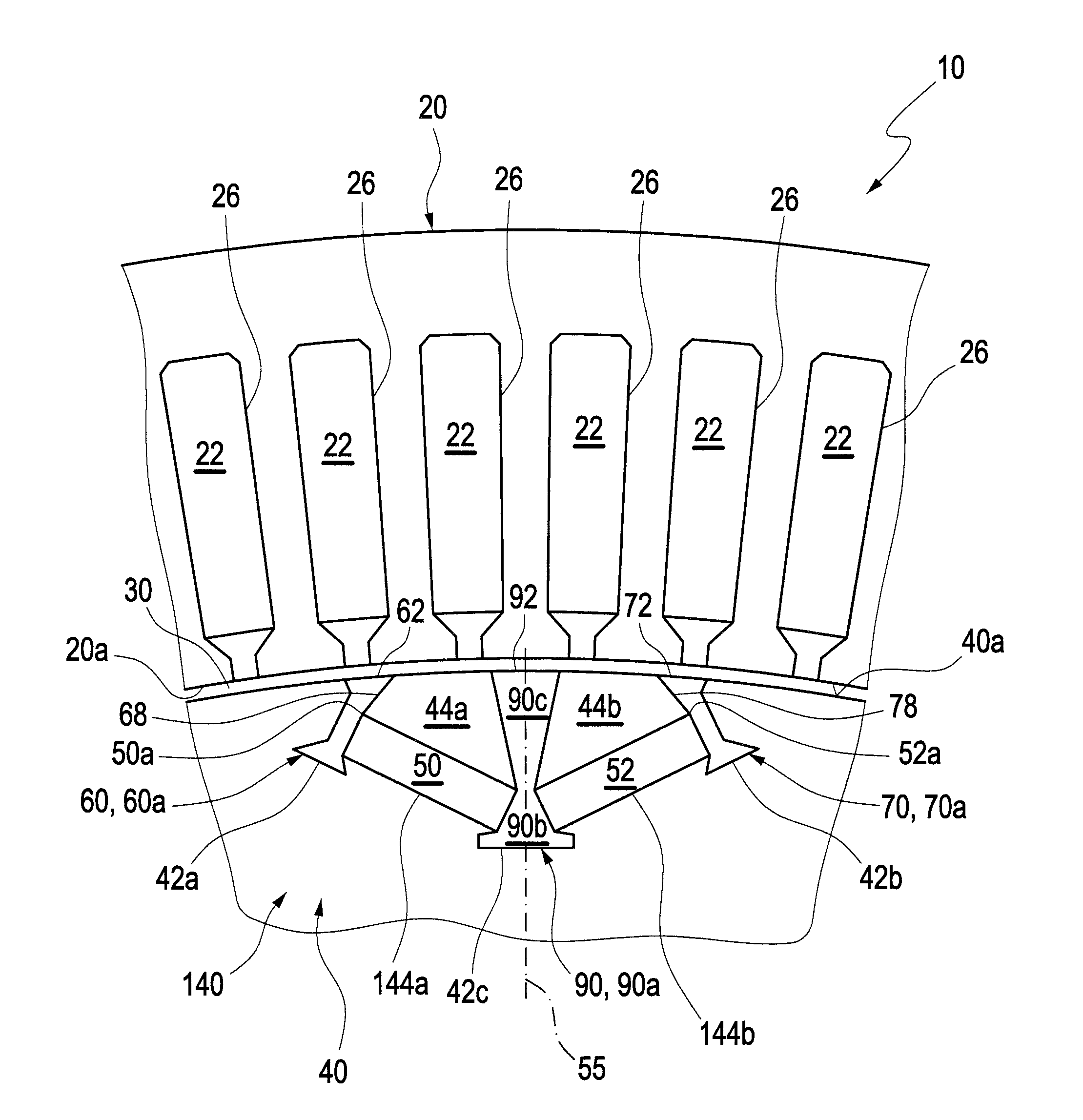
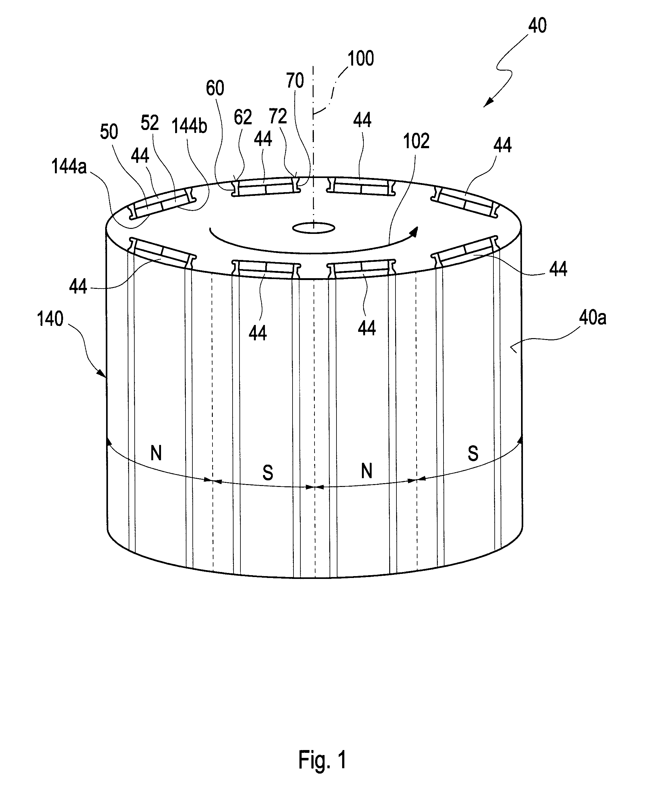
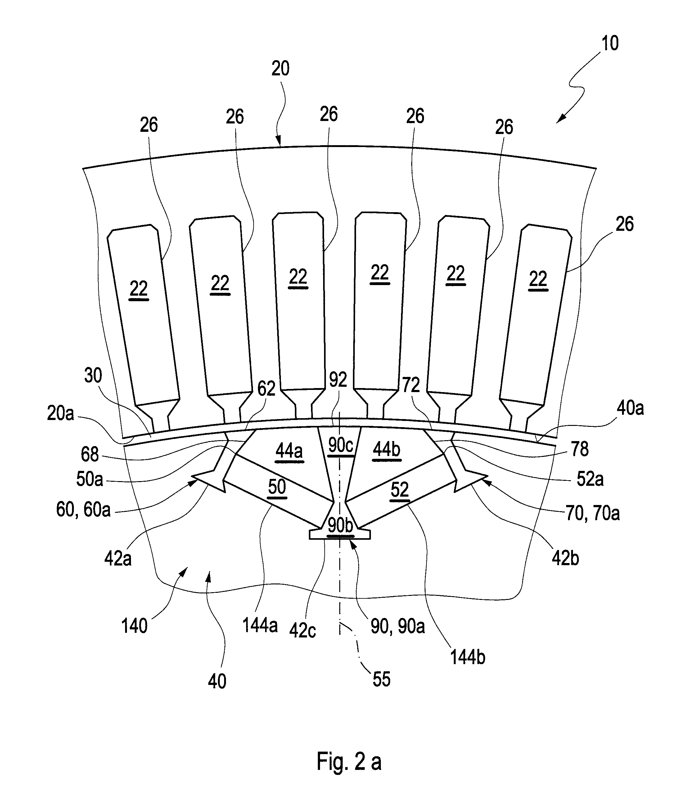
[0115]The embedded permanent magnets 250, 252 are arranged on the front face 240a of the disc-like rotor 240, the rotor 240 having a magnetic body 214, and they extend from an outer shell surface 240b of the rotor 240 towards an inner surface of an opening provided for a shaft in a way that the embedded permanent magnets 250, 252 are arranged in axial recesses with retainer elements 260 at each side of the embedded permanent magnets 250, 252. Seen from above, each of the embedded permanent magnets 250, 252 has a shape of a segment of a circle. Each embedded permanent magnet 250 has a neighbouring embedded permanent magnet 252 of opposite polarity. The shape of the embedded permanent magnets 250, 252 can have any shape, for instance the embedded permanent magnets 250, 252 can be cut...

second embodiment

[0117]FIGS. 14a-14c show a rotor 240 for an axial flux machine 200, as shown in FIG. 12, as front view (FIG. 14a), as cut view along line 14b-14b (FIG. 14b) and as side view (FIG. 14c).

[0118]The arrangement is similar to the arrangement described in FIG. 13a-13c except that the rotor 240 has embedded permanent magnets 250, 252 on both front faces of its magnetic body 214. The positions of the embedded permanent magnets 250, 252 on one rotor 240 are conformed on each side of the rotor 240.

[0119]Advantageously, rotors of electric machines comprising the retainer elements can provide higher performance with embedded permanent magnets and partially allow for a reduction of weight and magnetic losses in case the retainer elements are made of or comprise magnetically non-conductive material.


PUM


Abstract

A rotor for an electric machine excited by magnetic poles formed by one or more embedded permanent magnets includes a magnetic body and the one or more embedded permanent magnets associated with the magnetic body defining first magnetic poles and second magnetic poles of alternating magnetic polarity along a rotor direction. For at least one of the one or more embedded permanent magnets a rotor segment is arranged between the one or more embedded permanent magnets and a first surface of the magnetic body. At least one retainer element connects the rotor segment to a portion of the magnetic body.

Description

BACKGROUND AND SUMMARY[0001]The invention relates to a rotor for an electric machine exited by magnetic poles formed by one or more embedded permanent magnets and to an electric machine exited by such a rotor comprising poles formed by one or more embedded permanent magnets.[0002]Electric machines with permanent magnet (PM) rotors are known in the art. Such PM machines are employed as motors, as generators and as motor-generators. Various ways are known to integrate the permanent magnets in the rotor. PM machines comprising embedded permanent magnets are known to provide, among other things, higher saliency ratios, higher reluctance torque, increased protection against magnet demagnetization and, in case of internal rotor machines, the elimination of an external retaining sleeve around the rotor.[0003]There are generally three types of PM machines rotor topologies known in the art: surface magnet, inset magnet and embedded (buried, interior) magnet rotor topology. In the surface mag...

Claims


Application Information

Patent Timeline
IPC IPC(8): H02K1/27H02K1/28H02K1/276H02K1/278
CPCH02K1/2766H02K21/14H02K1/2793H02K21/24H02K1/28H02K1/04
Inventor CIRANI, MADDALENAERIKSSON, STURE
Owner VOLVO LASTVAGNAR AB
Why Eureka
Try Eureka