Motor for electrically regulating moving parts in motor vehicles and method for manufacturing motor

A technology for motor vehicles and components, applied in the field of manufacturing the motor, can solve the problem of not getting the prompt of the weight and torque density of the electric motor, and achieve the effects of high torque density, high power density, and power density optimization

Active Publication Date: 2015-04-29
ROBERT BOSCH GMBH
View PDF5 Cites 0 Cited by
  • Summary
  • Abstract
  • Description
  • Claims
  • Application Information

AI Technical Summary

Problems solved by technology

Here, the technician is not informed about the weight and torque density of the structural space-optimized electric motor to be provided

Method used


Image

  • Motor for electrically regulating moving parts in motor vehicles and method for manufacturing motor
  • Motor for electrically regulating moving parts in motor vehicles and method for manufacturing motor
  • Motor for electrically regulating moving parts in motor vehicles and method for manufacturing motor

Examples


Embodiment Construction

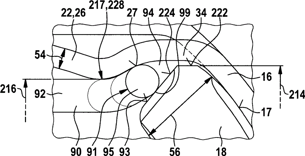
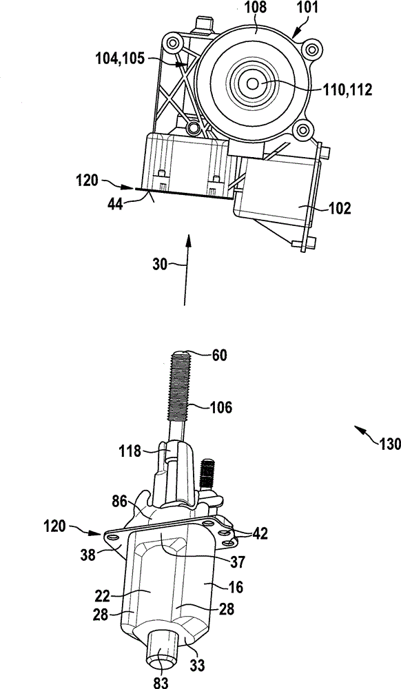
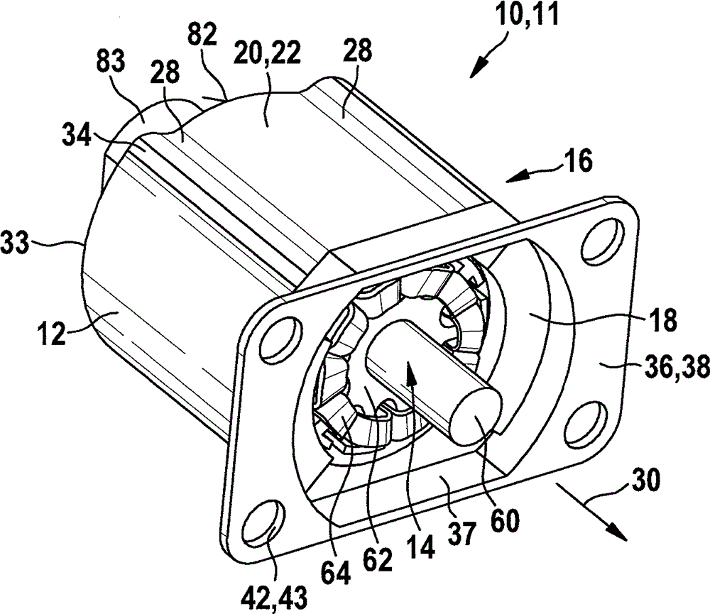
[0022] exist figure 1shows an electric machine 10 according to the invention, which is designed as an electric motor 11 . The electric motor 11 is, for example, a component of a transmission drive unit 130 as it is used to adjust a sliding sunroof, a window pane or a seat part in a motor vehicle. The electric machine 10 has a stator 12 in which two permanent magnets 18 are arranged opposite each other in a pole shoe 16 . The permanent magnet 18 can be designed as a ferromagnetic body, for example. Two opposing series poles 22 are arranged between two opposing permanent magnets 18 , which are formed by the housing wall 26 of the pole shoe 16 . For this purpose, two recesses 28 extending in the axial direction 30 are each formed in the truncated region 20 of the pole piece 16 . The series pole 22 is formed between two concave bends 28 in the circumferential direction 32 as an arcuate pole shoe wall 26 which forms a section of the pole shoe 16 together with the concave curve 2...


PUM


Abstract

The invention relates to a motor and method for manufacturing the motor. The motor is particularly used for electrically regulating moving parts in motor vehicles. The motor is provided with a stator (12), and a rotor (14) can be inserted into the stator. The stator (12) is provided with two opposite permanent magnets (18), and the permanent magnets are arranged in a pole shoe (16) forming a magnetic circuit. The pole shoe (16) is provided with an area (20) between the two permanent magnets (18), and a pole shoe wall (26) on the area forms two opposite magnetic tandem poles (22). The maximum width (214) of the middle axis (212) transverse to the permanent magnets (18) of the permanent magnets (18) is larger than the minimum spacing (216) between the opposite inner walls (217) of the pole shoe (16) in the area of the tandem poles (22).

Description

technical field [0001] The invention relates to an electric machine as claimed in the independent claims and to a method for producing the same. Background technique [0002] Document US 4,372,035 discloses an electric motor in which two opposing permanent magnets are arranged in a pole piece and two so-called series poles are arranged between the permanent magnets. To form the series poles, a profile is formed in the pole shoe wall, the curved inner surface of which has the same distance from the rotor as the profile of the shell-shaped permanent magnets. Here, the skilled person is not informed about the weight and torque density of the structural space-optimized electric motor to be provided. Contents of the invention [0003] The electrical machine according to the invention and the method according to the invention for producing such an electrical machine with the features of the independent claims accordingly have the advantage that the maximum width of the permanen...

Claims


Application Information

Patent Timeline
IPC IPC(8): H02K1/17H02K1/18H02K15/03
CPCH02K1/17H02K15/03H02K23/04
Inventor G.罗斯
Owner ROBERT BOSCH GMBH
Why Eureka
Try Eureka