Electric motor

A technology of electric motors and rotating components, which is applied in the direction of electric components, manufacturing motor generators, electromechanical devices, etc., can solve the problems of damaged motor acoustic performance, permanent magnet consumption, high total tolerance, etc., to improve operating characteristics and improve motor efficiency , the effect of small iron loss

Inactive Publication Date: 2020-11-17
BROSE FAHRZEUGTEILE GMBH & CO KG
View PDF4 Cites 0 Cited by
  • Summary
  • Abstract
  • Description
  • Claims
  • Application Information

AI Technical Summary

Problems solved by technology

Overall, this production of the permanent magnets is relatively complex and therefore expensive
Furthermore, due to the multi-part construction of the rotor and / or the manufacture of the rotor in several steps, the overall tolerances of the rotor are relatively high, which can adversely affect the statics of the motor and the acoustic performance of the motor

Method used


Image

  • Electric motor
  • Electric motor
  • Electric motor

Examples


Embodiment Construction

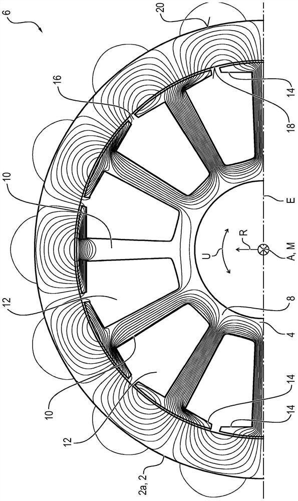
[0034] figure 1 The magnetic field line direction of the magnetic field between the rotor magnet 2a of the rotor 2 and the stator 4 of the brushless electric motor 6 is schematically shown. The rotor is supported in a manner capable of rotating around the motor axis M extending in the axial direction A. Here, for the purpose of better visibility of the magnetic field line direction, it is only partially shown. therefore, figure 1 Only half of the rotor 2 and the stator 4 are shown, wherein the unshown half of the rotor 2 and the stator 4 are mirror-symmetrical with respect to the plane E, the motor axis M extends through the plane, and the plane is perpendicular to the drawing Oriented flat.

[0035] The stator 4 has an annular stator yoke 8 from which stator teeth 10 extend away from the motor axis M toward the rotor 2 in a star-shaped manner, that is, in a radial direction R oriented perpendicular to the axial direction A. Therefore, the rotor 2 is arranged outside the stato...


PUM


Abstract

The invention relates to a brushless electric motor (6) having a stator (4) and having a rotor (2) which is drive-connected to a rotating element (28), wherein the rotor (2) has a permanent-magnet rotor magnet (2a) which is magnetized in the manner of a Halbach arrangement, wherein the rotor magnet (2a) is an injection-moulded part containing embedded magnetically anisotropic magnet material, which injection-moulded part is formed at least partially from a ferrite, and wherein the rotor (2) is integrated into the rotating element (28) or is joined to said rotating element.

Description

Technical field [0001] The present invention relates to a brushless electric motor, which has a stator and a rotor in a driving connection with a rotating element, wherein the rotor has a permanent magnet rotor magnet (ring magnet), and the rotor magnet is arranged in a Halbach-Anordnung manner magnetization. Background technique [0002] Brushless electric motors usually include a rotor (mover), and a relatively fixed stator is supported in a rotatable manner. For example, the stator here has a rotating magnetic field winding, and the rotating magnetic field winding generates a rotating magnetic field when loaded with alternating current. The rotor here has permanent magnets, and the magnetic field of the permanent magnets interacts with the rotating magnetic field of the stator, so that the rotor is driven to rotate. [0003] The permanent magnet is made of, for example, powder of magnetic material, such as powder of neodymium alloy or ferrite, by a sintering method. Here, the...

Claims


Application Information

Patent Timeline
Patent Type & Authority Applications(China)
IPC IPC(8): H02K7/14H02K1/27H02K21/22
CPCH02K1/2733H02K7/14H02K21/22H02K1/2792B29C45/17H02K15/03
Inventor 桑尼·张托马斯·苏塞米赫尔凯文·施泰纳特
Owner BROSE FAHRZEUGTEILE GMBH & CO KG
Why Eureka
Try Eureka