Permanent magnet synchronous motor with two stators, composite rotor structure and radial and axial mixed magnetic paths and method thereof

A technology of permanent magnet synchronous motor and composite structure, applied in the direction of motor, magnetic circuit, magnetic circuit rotating parts, etc., can solve the problems of increasing the amount of motor core material and manufacturing cost, vibration and noise, increasing manufacturing cost, etc.

Active Publication Date: 2016-07-20
SHANDONG UNIV
View PDF4 Cites 7 Cited by
  • Summary
  • Abstract
  • Description
  • Claims
  • Application Information

AI Technical Summary

Problems solved by technology

[0004] 1. The permanent magnet synchronous motor has a fixed permanent magnet magnetomotive force, and the main magnetic flux of the motor cannot be adjusted, resulting in a narrow constant power operating range and a wide range of speed regulation.
[0005] 2. In the existing built-in permanent magnet synchronous motor rotor structure, the permanent magnets of the rotor realize the "magnetism gathering effect" through various combinations, so the magnetic pole magnetic density of the rotor iron core is very high, so that there is a large leakage flux at the end, and the rotor The leakage flux is closed by the end of the motor rotor or the end cover. Since the total magnetic flux generated by the permanent magnet is constant, the existence of the leakage flux at the end not only makes the magnetic field distribution at the two ends of the motor uneven, but also reduces the effective flux of the motor. Utilization rate, thereby reducing the power density and torque density of the motor. In order to overcome the influence of the leakage flux at the end, the motor rotor often adopts an overhang structure in actual design, so that the axial length of the rotor core is greater than the axial length of the motor stator core. length, but this structure significantly increases the axial length of the motor, which in turn increases the amount of core material and manufacturing cost of the motor, and this structure does not essentially have the effect of suppressing the leakage flux at the end
[0007] 4. According to the different paths of the d-axis flux during field weakening, the existing permanent magnet synchronous motors with built-in rotor structure can be divided into two categories, one of which, when the field weakening control is performed, the d-axis generated by the armature winding The magnetic flux will pass through the permanent magnet of the motor, causing irreversible demagnetization of the permanent magnet. In the other category, when the field weakening control is performed, the d-axis magnetic flux generated by the armature winding is not closed by the permanent magnet, but the magnetic field generated by the d-axis current is forced More rotor flux closes through the ends of the motor and end caps, significantly increasing the leakage flux of the motor, and since the reluctance at the ends of the motor is usually much greater than the reluctance of the air gap, the required field weakening The d-axis current is high, which significantly increases the cost of the motor power inverter and the copper loss of the winding
[0008] 5. Existing permanent magnet synchronous motors usually have large armature back electromotive force harmonics and prominent cogging torque problems, which bring serious vibration and noise problems. At present, stator chute or rotor skew pole methods are usually used to improve back electromotive force. Electromotive force harmonics can weaken the cogging torque, but the processing technology of the stator chute and rotor slant pole is more complicated, which greatly increases the manufacturing cost, and will reduce the average electromagnetic torque of the motor to a certain extent, and reduce the torque density and power of the motor density

Method used


Image

  • Permanent magnet synchronous motor with two stators, composite rotor structure and radial and axial mixed magnetic paths and method thereof
  • Permanent magnet synchronous motor with two stators, composite rotor structure and radial and axial mixed magnetic paths and method thereof
  • Permanent magnet synchronous motor with two stators, composite rotor structure and radial and axial mixed magnetic paths and method thereof

Examples


Embodiment 1

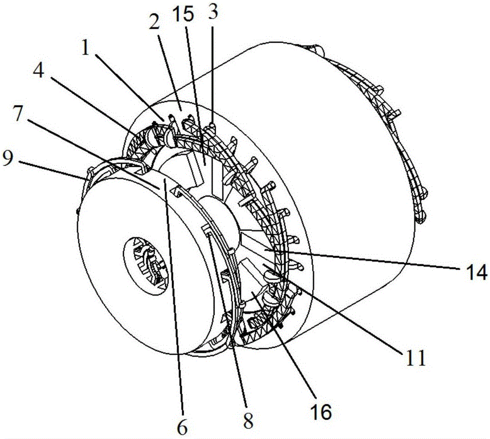
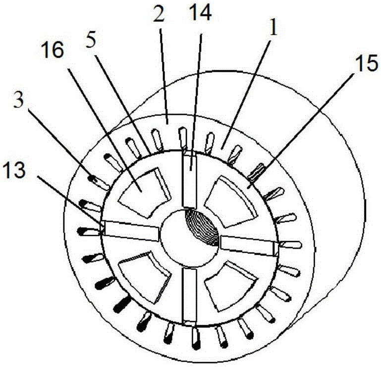
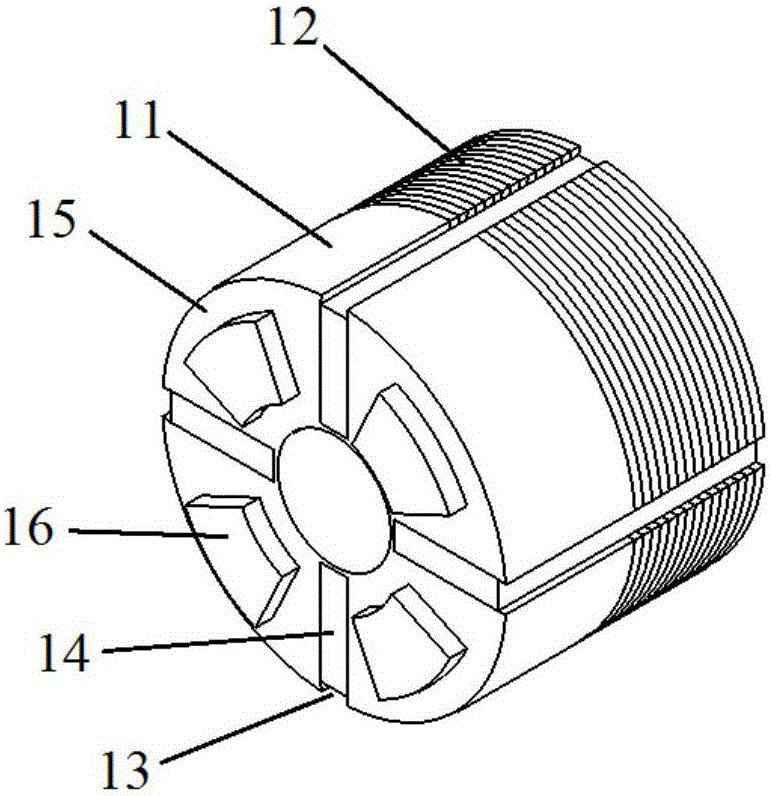
[0091] like Figure 1(a)-Figure 1(f) As shown, the number of motor phases in this embodiment is 3, the number of radial stator teeth is 24, the number of axial stator teeth is 12, the number of rotor slots is 4, the number of permanent magnet blocks is 4, the number of radial magnetic poles is 4, and the number of axial magnetic poles 4. This embodiment includes a radial stator, an axial stator and a rotor. The radial stator is made of laminated silicon steel sheets. The radial stator includes radial stator teeth 1, radial stator yokes 2 and radial stator slots 3. A radial armature winding 4 is placed in the radial stator slot 3, and the radial armature winding 4 can be a distributed winding, a concentrated winding or a stacked winding, and the number of poles of the radial armature winding is consistent with the number of radial magnetic poles of the rotor. The radial stator and the rotor are coaxial, and there is a radial air gap 5 between the radial stator and the rotor. The...

Embodiment 2

[0093] like Figure 2(a)-Figure 2(f)As shown, the main difference between Embodiment 2 and Embodiment 1 is that (1) there are axial stators at both ends of the motor in Embodiment 2, and both ends of the rotor core of the motor are processed into salient pole fans The shape of the ring forms the axial magnetic poles. (2) The compound rotor in the second embodiment is composed of three parts, the middle is a silicon steel sheet rotor, and the two ends are solid rotors. (3) The arrangement of the permanent magnets in the second embodiment is the same as that in the first embodiment. The difference is that the permanent magnets in the first embodiment have a single parallel structure, while the permanent magnets in the second embodiment have a series-parallel structure. In this embodiment, the number of motor phases is 3, the number of radial stator teeth is 24, the number of axial stator teeth is 12, the number of rotor slots is 4, the number of permanent magnet blocks is 4, the...


PUM


Abstract

The invention discloses a permanent magnet synchronous motor (PMSM) with two stators, a composite rotor structure and radial and axial mixed magnetic paths and a method thereof. The PMSM comprises a radial stator, an axial stator and a rotor, wherein the rotor is inserted in the radial stator and coaxially arranged with the radial stator, the axial stator is arranged on one end or two ends of the rotor, the axial stator and the rotor are concentric, a radial winding is arranged in the stator groove of the radial stator, an axial winding is arranged in the stator groove of the axial stator, a rotor groove is arranged in the rotor, a permanent magnet is placed in the rotor groove, the permanent magnet enables the rotor to generate a radial magnetic pole and an axial magnetic pole, the radial magnetic pole faces the radial stator of the motor, the axial magnetic pole faces the axial stator of the motor, and the motor generates radial and axial torques to form mixed magnetic paths. The radial magnetic flux and axial magnetic flux generated by the permanent magnet of the motor can be utilized, end portion magnetic leakage can be eliminated, the utilization rate of motor material is improved, and the weight of the motor is reduced.

Description

technical field [0001] The invention relates to a permanent-magnet synchronous motor with a double-stator composite structure rotor radial and axial hybrid magnetic circuit and a method. Background technique [0002] In recent years, with the improvement of high temperature resistance and price reduction of permanent magnet materials, permanent magnet motors have been more widely used in national defense, industrial and agricultural production, and daily life, and are moving towards high power, high performance and miniaturization. direction of development. At present, the power of permanent magnet motors ranges from a few milliwatts to several thousand kilowatts, and its application ranges from toy motors, industrial applications to large permanent magnet motors for ship traction, and has been widely used in various aspects of the national economy, daily life, military industry, and aerospace. widely used. [0003] However, the existing permanent magnet synchronous motor ...

Claims


Application Information

Patent Timeline
Patent Type & Authority Applications(China)
IPC IPC(8): H02K1/27H02K1/16H02K3/28H02K1/26H02K16/04
CPCH02K1/165H02K1/265H02K1/2746H02K3/28H02K16/04Y02T10/64
Inventor 王道涵
Owner SHANDONG UNIV
Why Eureka
Try Eureka