Sensor assembly and method for determining a magnetization direction of an indicator magnet

a technology of indicator magnets and sensor assemblies, which is applied in the direction of converting sensor output, measuring devices, instruments, etc., can solve the problems of large disadvantages, insufficient utilization of the theoretically possible travel range between sensors and permanent magnets, and relatively easy implementation of evaluations. , to achieve the effect of increasing the robustness of the measurement assembly, enlarging the practicable travel range, and increasing the robustness

Active Publication Date: 2013-01-31
FRAUNHOFER GESELLSCHAFT ZUR FOERDERUNG DER ANGEWANDTEN FORSCHUNG EV
View PDF2 Cites 41 Cited by
  • Summary
  • Abstract
  • Description
  • Claims
  • Application Information

AI Technical Summary

Benefits of technology

[0015]It is a finding of the present invention that the just stated enlargement of the travel range of the indicator magnet with respect to the sensor assembly, with simultaneously increased robustness with regard to external spurious influences can be obtained, for example by using a four-quadrant evaluation method, as it will be described in more detail in the invention, by determining the magnetization direction of the indicator magnet based on the determined position of the indicator magne...

Problems solved by technology

This type of evaluation is relatively easy to implement but has great disadvantages during application.
However, there is the general problem that also in this method according to FIG. 12, the travel range is no...

Method used


Image

  • Sensor assembly and method for determining a magnetization direction of an indicator magnet
  • Sensor assembly and method for determining a magnetization direction of an indicator magnet
  • Sensor assembly and method for determining a magnetization direction of an indicator magnet

Examples


Embodiment Construction

[0034]Before the present invention will be discussed below in more detail based on the Figures, it should be noted that in the following embodiments the same elements or functionally equal elements are provided with the same reference numbers in the figures. Thus, a description of elements having the same reference numbers is inter-exchangeable and / or applicable in the different embodiments.

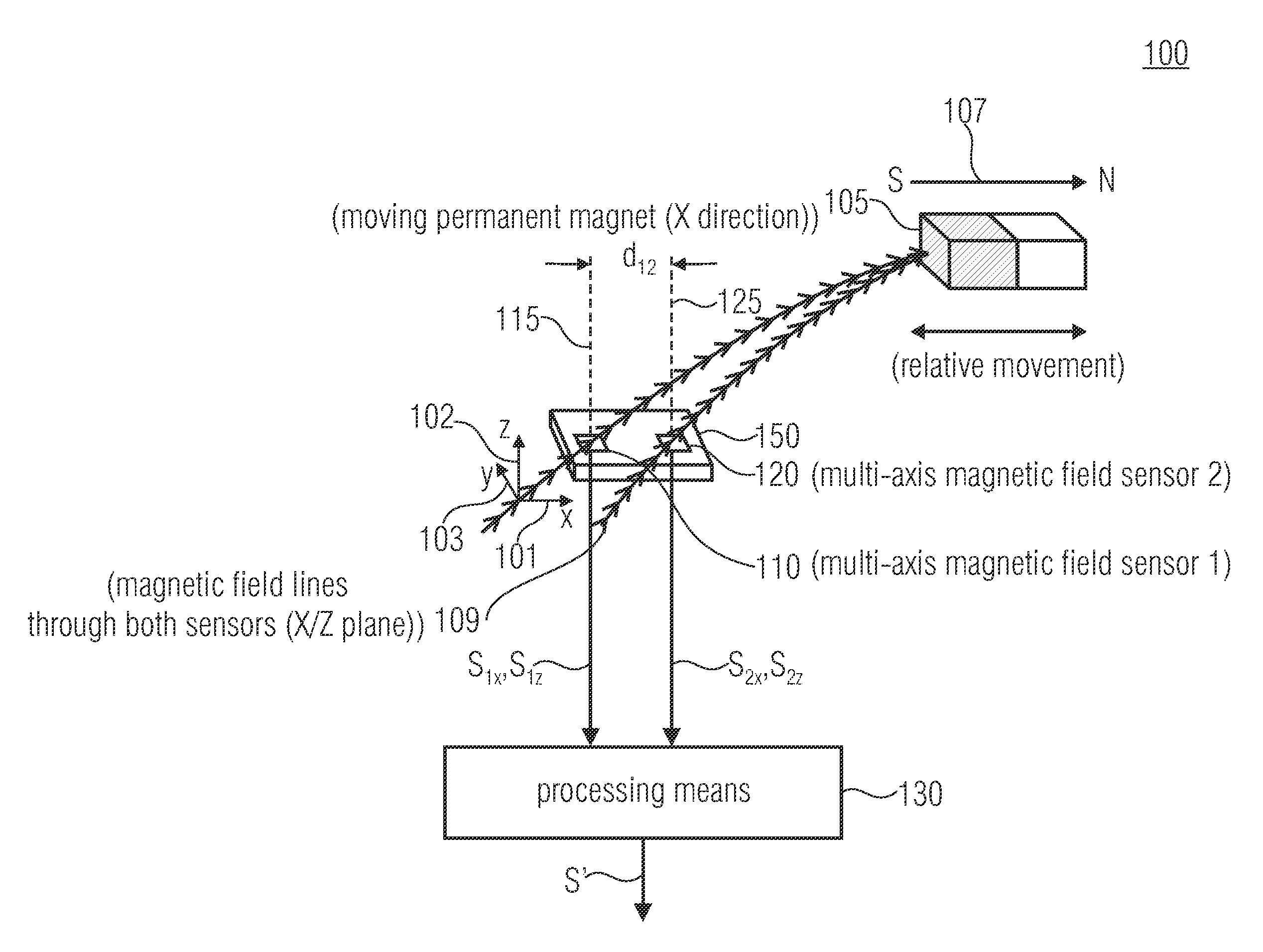
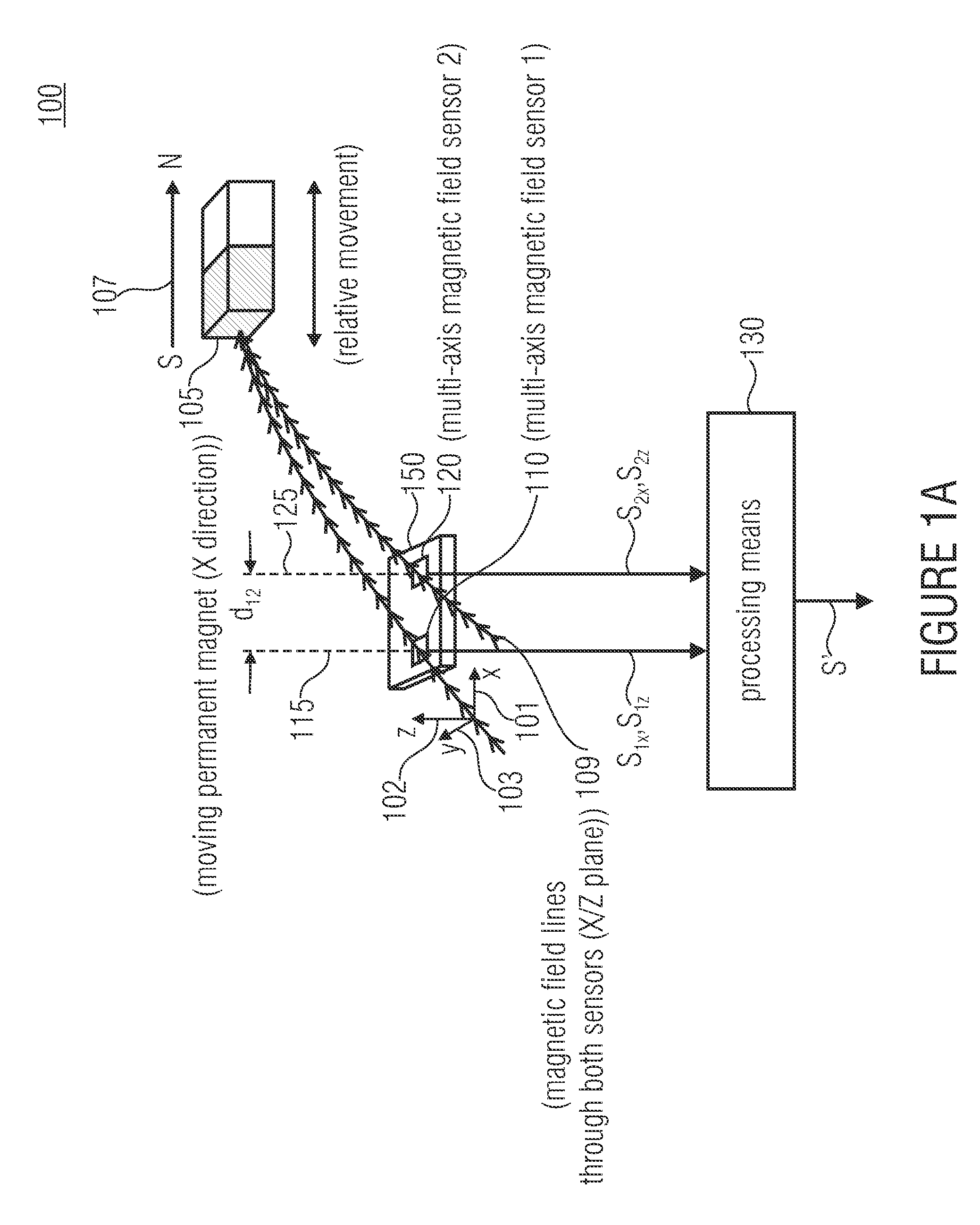
[0035]FIG. 1a shows a sensor assembly 100 for position determination of an indicator magnet, which can also be referred to as encoder magnet or sensor magnet or position magnet 105, according to an embodiment of the present invention. As shown in FIG. 1a, the sensor assembly 100 comprises a first magnetic field sensor 110, a second magnetic field sensor 120 and a processing means 130. The first magnetic field sensor 110 and the second magnetic field sensor 120 can in particular be implemented as multi-axis magnetic field sensors, such as a combination of magnetic field sensors sensitive with resp...


PUM


Abstract

A sensor assembly for determining a magnetization direction of an indicator magnet with respect to the sensor assembly includes a first magnetic field sensor for detecting a first and a second magnetic field component with respect to a first and a second spatial direction, and a second magnetic field sensor for detecting a third and a fourth magnetic field component with respect to the second spatial direction, wherein the first and the second magnetic field sensor are spaced apart from one another. Further, the sensor assembly includes a processor that is implemented to combine the first and the second magnetic field component to obtain a first combination quantity, to combine the third and the fourth magnetic field component to obtain a second combination quantity, to determine a position of the indicator magnet and the magnetization direction.

Description

CROSS-REFERENCE TO RELATED APPLICATIONS[0001]This application is a continuation of copending International Application No. PCT / EP2011 / 053917, filed Mar. 15, 2011, which is incorporated herein by reference in its entirety, and additionally claims priority from German Application No. DE 10 2010 003 292.1, filed Mar. 25, 2010, which is also incorporated herein by reference in its entirety.BACKGROUND OF THE INVENTION[0002]Embodiments of the invention relate to a concept for determining a magnetization direction of an indicator magnet. Further embodiments of the invention relate to automatic detection of the magnetization direction in position measurement systems on a magnetic basis.[0003]In the field of linear position measurement system on a magnetic basis, it has long been common to use Hall sensors in connection with moving permanent magnets to monitor single axis linear movements. In principle, such systems are structured as shown in FIG. 10. There is a fixed sensor 10 across which ...

Claims


Application Information

Patent Timeline
IPC IPC(8): G01B7/14
CPCG01D5/145
Inventor HOHE, HANS-PETERSAUERER, JOSEF
Owner FRAUNHOFER GESELLSCHAFT ZUR FOERDERUNG DER ANGEWANDTEN FORSCHUNG EV
Why Eureka
Try Eureka