Signal measuring system, method for electrically conducting signals and a signal cable

a signal measurement and signal cable technology, applied in the direction of noise figure or signal-to-noise ratio measurement, instruments, applications, etc., can solve the problems of unwanted signal, mechanical stress of the signal cable, noise that may be added, etc., to reduce the effect of noise on the signal quality and not increase the power usage or power loss

Active Publication Date: 2013-01-31
KONINKLIJKE PHILIPS ELECTRONICS NV
View PDF21 Cites 10 Cited by
  • Summary
  • Abstract
  • Description
  • Claims
  • Application Information

AI Technical Summary

Benefits of technology

[0007]It is an object of the present invention to reduce the effect of noise on the signal quality caused by movement of a signal cable or other sources of noise that induce a noise signal in the signal cable, such as electromagnetic interference, while at the same time not increasing the power usage or power loss. This object is achieved by the signal measurement system according to the invention, in which the system comprises:
[0024]In a preferred embodiment of the method according to the invention the method further comprises the step of controlling a measurement of the raw signal based on the noise signal. In this way a feedback loop is provided in which the noise signal, which is available via the reference conductor, is an input parameter for the control of the measurement process of the raw signal, which is, for example a sensor. In a preferred embodiment the step of controlling comprises a step of initiating the measurement of the raw signal if the detected noise signal is below a selected threshold. In this way the measurement of the raw signal only is performed if there is hardly any movement of the cable and, thus, the noise signal is low, resulting in a reduction of the disturbance of the first signal by a noise signal. This increases the accuracy of the measurement of the raw signal. In another preferred embodiment the step of controlling comprises a step of shutting down an ongoing measurement of the raw signal, if the detected noise signal is above or equal to a selected threshold. In this way the measurement of the raw signal is not performed if there is, for example, a non-negligible movement of the cable and, thus, the noise signal is relatively high, which would result in an increase of the disturbance of the first signal by a noise signal.
[0028]The reference conductor according to the invention provides for a simple measurement of the noise signal induced by, for example, a tribo-electric effect caused by a movement of the signal cable without adding any voltage or current signal to the reference conductor, thereby not increasing the power consumption in the signal cable. The noise signal is thus separately available for any further processing of the signals via the reference conductor. The reference conductor is able to detect movement of the signal cable, because a noise signal is generated in the reference conductor in case the cable moves, for example bends or stretches, induced by, for example, a tribo-electric effect or by electromagnetic interference.
[0032]In a preferred embodiment of the signal cable the reference conductor also conducts a second signal. In this way no extra conductor is required and use is made of a conductor which is already used for another purpose, for example for conducting a control signal.

Problems solved by technology

One of the sources of noise that may be added to the signal during transport of the signal in the signal cable is tribo-electricity.
Movement of a signal cable, for example due to handling of the signal cable or due to movement of the source or load to which the signal cable is connected, leads to mechanical stress of the signal cable, such as bending, compression or stretching, which influences the internal geometry of the signal cable.
This may lead to the tribo-electric effect in the signal cable in which electric charge is created which causes an additional, unwanted signal onto the raw signal and can have a significant impact on the signal to noise ratio of the raw signal.
Another source of noise is the change of the value of the coupling capacity between individual wires in the cable, between wires and shielding or between wires and surrounding environment of the cable.
The changed value of the capacity can lead to electric charge, thus adding noise to the raw signal.
Another source of noise is the change of electrical resistance of wires or shielding induced by cable movement.
Also the change of the permeability or susceptibility of the insulator material induced by motion or acceleration can add noise to the raw signal.
Furthermore, movement of the cable can change its position with respect to the surrounding environment and in this way change the permeability or susceptibility, again adding noise to the raw signal.
Next to noise generated by a movement of the cable, also other sources can affect the signal in the signal cable by introducing additional noise, such as for example electromagnetical interference.
Any movement of the signal cables used in this patient monitoring induces a noise signal that is mixed with or added to the raw physiological signal in the signal cable, and affects the signal to noise ratio of the raw physiological signal.
Especially in the case of mobile patients, wearing a physiological signal detection unit such as a pulse oximeter for measuring the oxygen saturation of the blood, the signal cable is subjected to movements, like bending, stretching, thereby inducing tribo-electric and other effects in the signal cable that is attached to the signal detection unit and thus adding noise to the raw signal.
This cable design reduces tribo-electric effects in an active way, thus increasing the power consumption of the cable.

Method used


Image

  • Signal measuring system, method for electrically conducting signals and a signal cable
  • Signal measuring system, method for electrically conducting signals and a signal cable
  • Signal measuring system, method for electrically conducting signals and a signal cable

Examples


Embodiment Construction

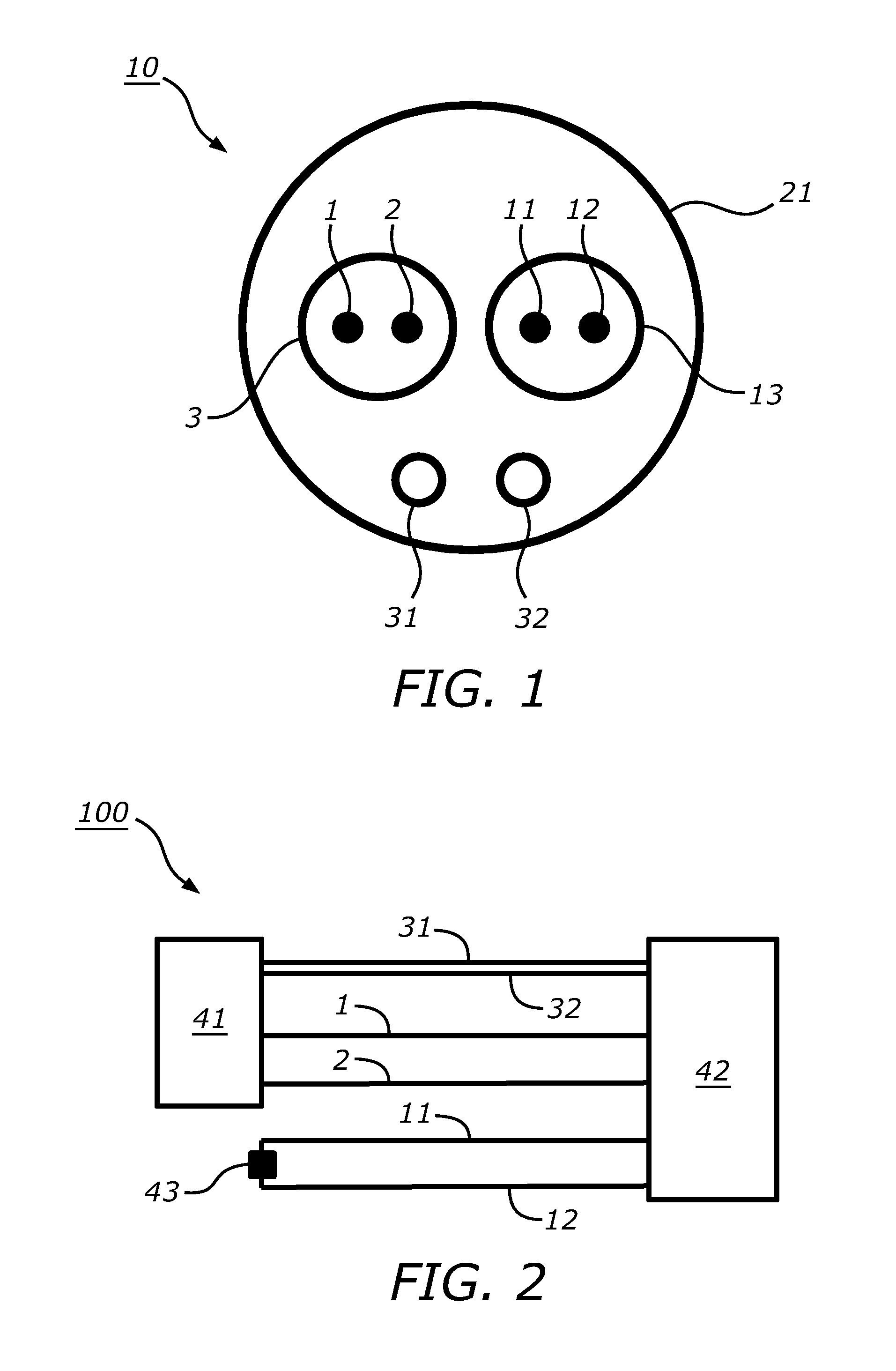
[0038]FIG. 1 shows a schematic cross-section of a signal cable 10 according to the invention. The signal cable 10 comprises, in this embodiment, a first signal lead 1 and a second signal lead 2 surrounded by a first shielding 3. The first signal lead 1 and the second signal lead 2 are adapted to electrically conduct a first signal and, in combination with the first shielding 3, form a signal conductor. The first signal may be any electrical signal, such as a voltage signal or a current signal that varies in amplitude as a function of time. For example, the first signal comprises a raw signal that is measured by a sensor and that has to be transported from the sensor to a signal processing unit via the signal cable 10. The signal cable 10 further comprises a first reference lead 11 and a second reference lead 12 surrounded by a second shielding 13. The combination of the first reference lead 11, the second reference lead 12 and the second shielding 13 forms a reference conductor. The...


PUM


Abstract

The present invention relates to a signal measurement system (100, 200, 300) for measuring a signal, the system comprising a signal detection unit (41) for detecting a raw signal, a signal processing unit (42) and a signal cable (10) electrically connecting the signal detection unit (41) with the signal processing unit (42). The signal cable (10) comprises a signal conductor (1, 2) for electrically conducting a first signal from the signal detection unit (41) to the signal processing unit (42), which first signal comprises at least the raw signal, a reference conductor (11, 12) for detecting and electrically conducting to the signal processing unit (42) only a noise signal induced by a movement of the signal cable (10) or by electromagnetic interference. In this way the effect of noise on the signal quality is reduced caused by movement of the signal cable (10) or other sources of noise that induce a noise signal in the signal cable (10), such as electromagnetic interference, while at the same time not increasing the power usage or power loss.

Description

FIELD OF THE INVENTION[0001]The invention relates to a signal measuring system, method for electrically conducting signals and a signal cable.BACKGROUND OF THE INVENTION[0002]Signal cables are used to transport signals from a source, such as a detector, sensor or microphone, to a load, such as a signal processing unit or a pre-amplifier. The signal cable must be able to transfer the signal without adding any disturbance or noise to the signal, because the disturbance or noise could change the amplitude, frequency or any other characteristic of the signal. In other words, the signal and its characteristics that are input at one end of the signal cable should be the same as the signal and its characteristics that are output at the opposite end of the signal cable.[0003]One of the sources of noise that may be added to the signal during transport of the signal in the signal cable is tribo-electricity. The tribo-electric effect is an electrical phenomenon in which certain materials can b...

Claims


Application Information

Patent Timeline
Patent Type & Authority Applications(United States)
IPC IPC(8): G01R29/26A61B5/308
CPCA61B5/14551G01R1/24G01R1/18A61B5/7203
Inventor DUBIELCZYK, ALEXANDERSCHWENK, MARCUS
Owner KONINKLIJKE PHILIPS ELECTRONICS NV
Why Eureka
Try Eureka