Circuit and method for detecting multiple supply voltages

a technology of supply voltage and circuit, applied in the direction of power supply testing, pulse technique, instruments, etc., can solve the problems of undoubtedly huge power consumption of the whole circuit, abnormal operation of the system,

Active Publication Date: 2013-01-31
SEMICON COMPONENTS IND LLC
View PDF6 Cites 17 Cited by
  • Summary
  • Abstract
  • Description
  • Claims
  • Application Information

AI Technical Summary

Benefits of technology

[0009]By the present invention, multiple supply voltages can be detected using two comparators, which solves the problem that power consumption of existing circuit for detecting multiple supply voltages is huge in the related art, reduces the number of comparators and improves the performance of the system.

Problems solved by technology

The voltage of a battery will drop in a curve form when the power of the battery is insufficient, and too low of a voltage possibly leads to an abnormal operation of the system.
Due to the power consumption of each comparator, in a circuit for detecting multiple supply voltages, the power consumption of the whole circuit will be undoubtedly huge if multiple comparators are used to detect multiple supply voltages.

Method used


Image

  • Circuit and method for detecting multiple supply voltages
  • Circuit and method for detecting multiple supply voltages
  • Circuit and method for detecting multiple supply voltages

Examples


example 1

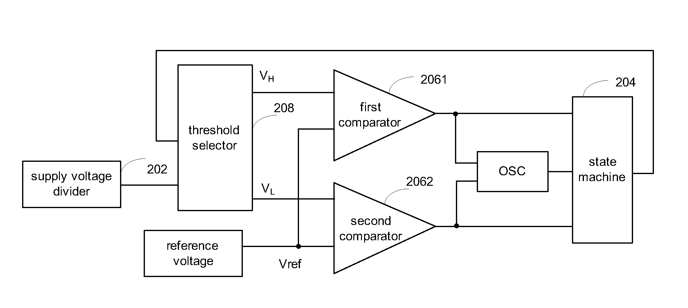
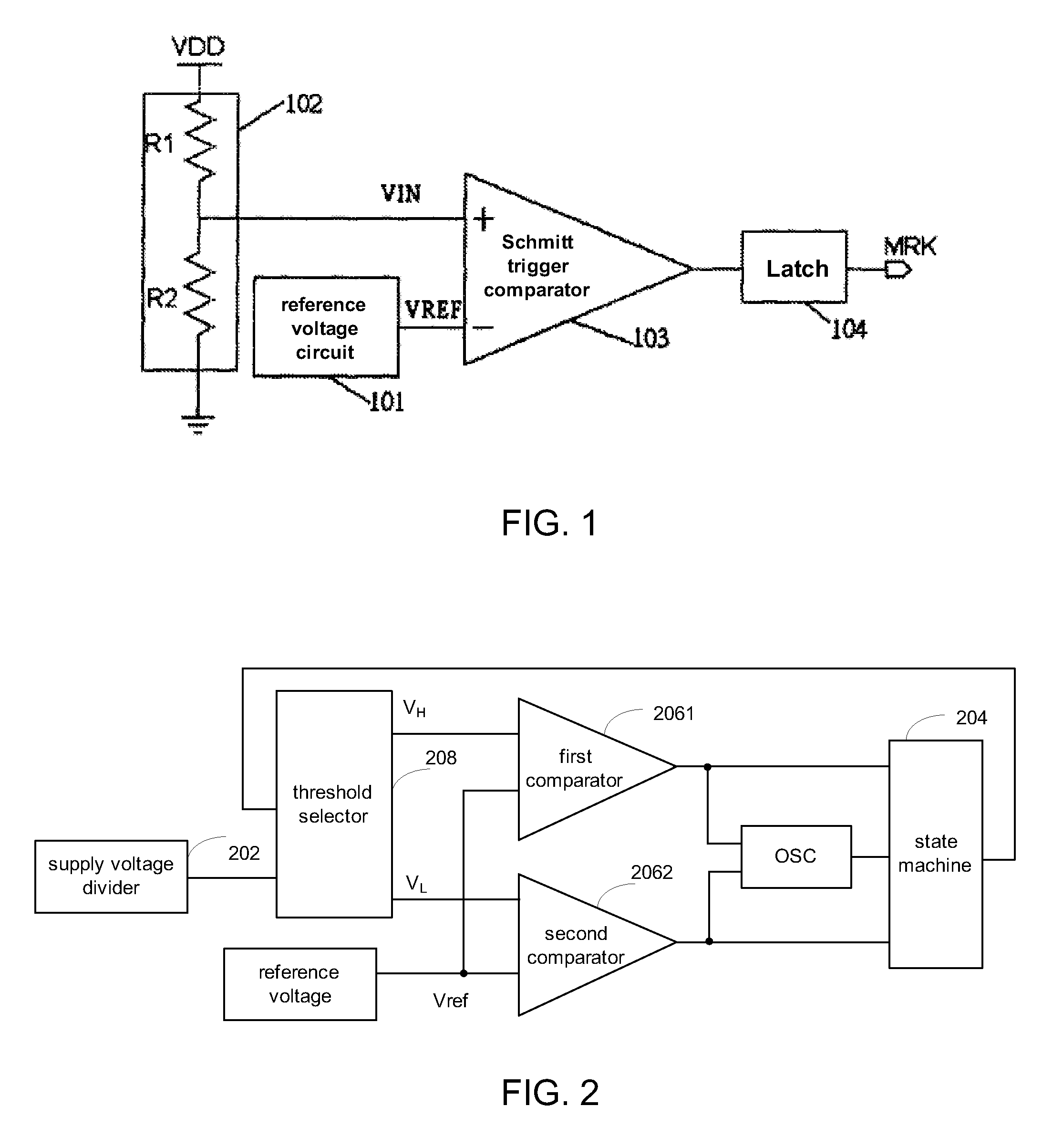
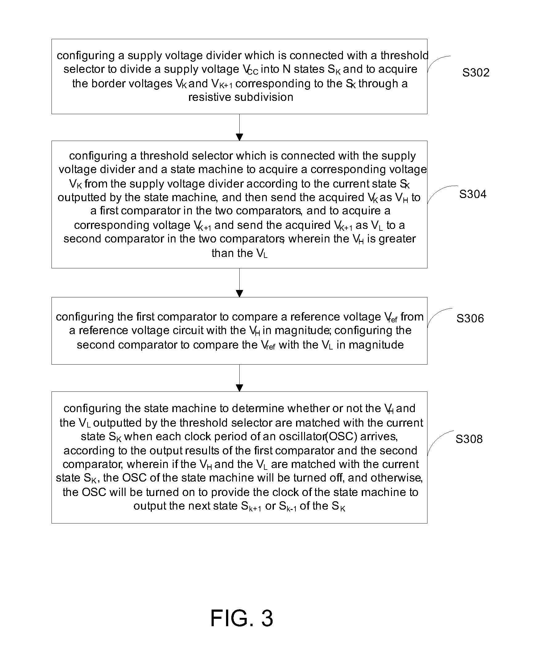
[0059 includes subject matter such as a circuit for detecting multiple supply voltages comprising a supply voltage divider, a state machine, two comparators and a threshold selector. The supply voltage divider, connected with the threshold divider, is configured to divide a supply voltage VCC into N states SK, and to acquire the border voltages VK and VK+1 corresponding to the SK through a resistor divider, wherein K=1, 2, . . . N; the threshold selector, connected with the supply voltage divider and the state machine, is configured to acquire a corresponding voltage VK from the supply voltage divider according to the current state SK outputted by the state machine, and then send the acquired VK as VH to a first comparator in the two comparators, and to acquire a corresponding voltage VK+1 and send the acquired VK+1 as a VL to a second comparator in the two comparators, wherein the VH is greater than the VL, the first comparator is configured to compare a reference voltage Vref from...


PUM


Abstract

An apparatus comprises a supply voltage divider, a state machine, two comparators and a threshold selector. The supply voltage divider divides a VCC into N states SK, and acquires the border voltages VK and VK+1 corresponding to the SK through a resistor divider. The threshold selector acquires a corresponding voltage VK from the supply voltage divider according to the current state SK outputted by the state machine and then sends the acquired VK as VH to a first comparator, and acquires a corresponding voltage VK+1 and sends the acquired VK+1 as VL to a second comparator. The state machine determines whether or not the VH and the VL are matched with the current state SK. If matched, the OSC of the state machine will be turned off, otherwise, the next state Sk+1 or Sk−1 of the SK will be outputted.

Description

RELATED APPLICATION[0001]The present application claims the benefit of priority to Chinese Patent Application Serial No. 201110111780.3, filed on Apr. 29, 2011, which is hereby incorporated by reference herein in its entirety.BACKGROUND OF THE INVENTION[0002]The power supply voltage of an electronic system often undergoes a decrease in voltage, especially when being powered by a battery. The voltage of a battery will drop in a curve form when the power of the battery is insufficient, and too low of a voltage possibly leads to an abnormal operation of the system. Thus, an electronic system is usually provided with a circuit for detecting supply voltage to avoid the voltage too low.[0003]FIG. 1 is a schematic diagram of a circuit for detecting supply voltages according to the related art, and as shown in FIG. 1, the circuit for detecting supply voltage consists of a reference voltage circuit 101, a resistor divider circuit 102, a Schmitt trigger comparator 103 and a latch 104, wherein...

Claims


Application Information

Patent Timeline
Patent Type & Authority Applications(United States)
IPC IPC(8): H03K5/153G01R31/40G01R19/165
CPCG01R19/16595G01R19/16552G01R31/40G01R15/04G01R19/16566G01R19/1659G08C19/02
Inventor HUANG, LEI
Owner SEMICON COMPONENTS IND LLC
Why Eureka
Try Eureka