Router, method for controlling router, and program
a router and router technology, applied in the field of routers and router methods, can solve the problems of increasing the difficulty of designing an integrated circuit by such the scale of the circuit has become even larger, and it is increasingly difficult to design an integrated circuit. a centralized bus control can solve the problem of traffic flow through the transmission path, and achieve the effect of preventing traffic flow, improving overall transfer performance (including throughput and time delay), and increasing the implementation area or power dissipation
- Summary
- Abstract
- Description
- Claims
- Application Information
AI Technical Summary
Benefits of technology
Problems solved by technology
Method used
Image
Examples
embodiment 1
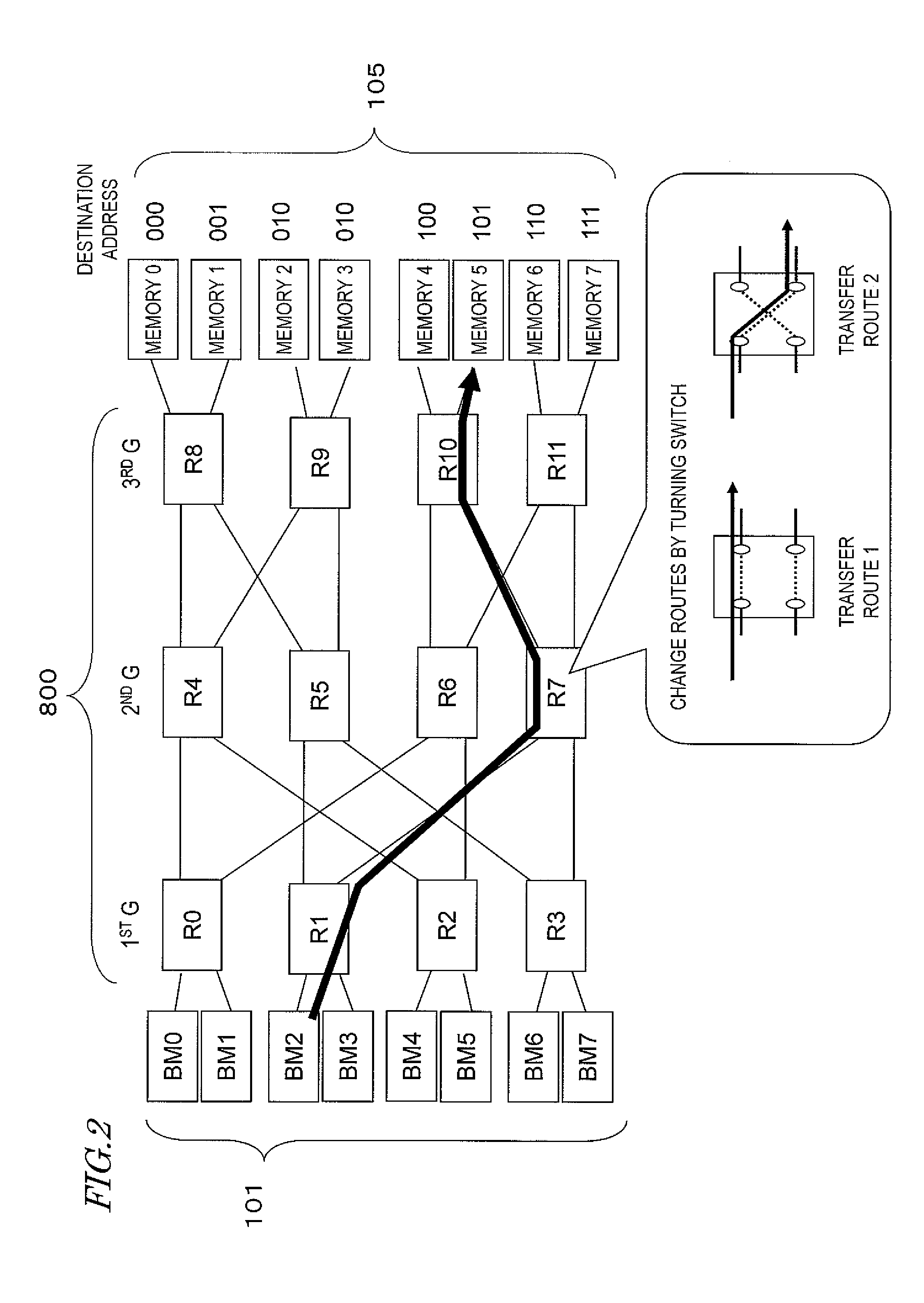
[0098]FIG. 2 illustrates an exemplary configuration for a distributed data transfer system that uses routers according to a first embodiment of the present disclosure. The system shown in FIG. 2 includes a plurality of bus masters (BMs) 101 as transmitting nodes and a plurality of memories 105 as receiving nodes. Those bus masters 101 and memories 105 are connected together in multiple stages with a bus via a number of routers 800. In this manner, the transfer system shown in FIG. 2 forms a multistage interconnection network (MIN). In this embodiment, those bus masters 101 function as first nodes according to the present disclosure and those memories 105 function as second nodes according to the present disclosure.
[0099]In this embodiment, the bus masters 101 are devices that can perform a data transfer control using a bus and may be CPUs (central processing units) or DSPs (digital signal processors), for example. The memories 105 may be semiconductor memories such as DRAMs or SRAMs...
embodiment 2
[0202]Hereinafter, a second embodiment of the present disclosure will be described.
[0203]The router of this embodiment has quite the same components as the counterpart of the first embodiment described above except that the number of virtual channels used comparing section 811 performs its processing differently. Thus, the following description of this embodiment will be focused on only that difference from the first embodiment and their common features will not be described all over again to avoid redundancies.
[0204]According to the first embodiment described above, traffic flows are distinguished by their destination and the number of virtual channels used in respective routers on the transmission path can be made uniform on a traffic flow basis. As a result, it is possible to avoid an unwanted situation where every virtual channel in a particular router on the transmission path is occupied by a particular traffic flow to prevent a traffic flow with any other destination from bein...
embodiment 3
[0223]Hereinafter, a third embodiment of the present disclosure will be described.
[0224]According to the first and second embodiments described above, traffic flows are distinguished by their destinations and allocation of virtual channels is controlled so that the numbers of virtual channels used become as uniform as possible among respective routers on the transmission path. As a result, it is possible to prevent a traffic flow headed to any particular destination from occupying every virtual channel in the router and causing a decline in transfer performance.
[0225]According to this embodiment, a number of packets with the same destination specified, which are saved in multiple virtual channels in a router, have their order of transmission controlled by reference to the time information added to those packets. In this manner, each traffic flow can be transferred with its quality concerning the time delay improved.
[0226]Generally speaking, the maximum amount of time allowed a packe...
PUM
 Abstract
Description
Claims
Application Information
 - R&D
- Intellectual Property
- Life Sciences
- Materials
- Tech Scout
- Unparalleled Data Quality
- Higher Quality Content
- 60% Fewer Hallucinations
Browse by: Latest US Patents, China's latest patents, Technical Efficacy Thesaurus, Application Domain, Technology Topic, Popular Technical Reports.
© 2025 PatSnap. All rights reserved.Legal|Privacy policy|Modern Slavery Act Transparency Statement|Sitemap|About US| Contact US: help@patsnap.com


