Multiwell strips

a multi-well strip and strip technology, applied in the field of multi-well strips, can solve the problems of low stiffness of pp, prone to heat distortion, and difficult handling of prior art multi-well strips, and is not suited for automated procedures recruiting robotics

Inactive Publication Date: 2013-01-31
4TITUDE
View PDF4 Cites 26 Cited by
  • Summary
  • Abstract
  • Description
  • Claims
  • Application Information

AI Technical Summary

Benefits of technology

[0016]A further possibility to modify the thermal diffusivity is the thickness of the material. The thinner a material is the faster the temperature of the surroundings is transferred into the inner portion of the well. Thus the wells (3) of the multiwell strip (1) are relatively thin to facilitate optimal thermal transfer to samples during thermal cycling procedures. In a preferred embodiment the receiving portions (5) of the wells (3) have a wall-thickness of 0.05 mm to 0.5 mm, preferably 0.15 mm to 0.4 mm, even more preferred is an average wall-thickness of 0.25 mm. Depending on the material also thinner walls may be possible and are likewise preferred. The skilled artisan will appreciate that by the thin walls and the materials used the multiwell strip (1) according to the present invention permits use of optical detection systems for optically analyzing samples through sample well bottoms.
[0019]The skilled artisan will unambiguously recognize that the multiwell strip (1) according to the present invention by providing the stiff frame can easily be handled manually as well as by robotic and automated devices. However, the handling may be eased by adding a frame wall (6) to at least one side of the frame. The frame wall (6) may extend from the planar top surface of the frame portion (2) to the bottom of the multiwell strip (1) or it may be shorter so that the bottom of the wells (3) form the bottom of the strip. Multiwell strips are often handled at the narrow sides as they are easily accessible when several multiwell strips are placed e.g. in a thermocycler. Thus, in a preferred embodiment of the present invention the frame portion (2) comprises a frame wall (6) at one or both of its narrow sides and in a further embodiment the frame portion (2) comprises a frame wall (6) at one or both of its long sides.
[0034]The skilled person is able to design and construct “predetermined breaking lines” and is able to determine the fortitude needed to provide both, a multiwell-frame (7) according to the invention with a connection fortitude suited for a save transportation of the multiwell-frame (7) and an easy manual division of the strips. In a preferred embodiment the predetermined breaking lines (9) are designed for manual dividing of the multiwell-frame.
[0070]The features of the present invention allow for an easy handling of multiwell strips (1) manually as well as automatically. Thus the present invention also relates to the use of a multiwell strip (1) according to the present invention or a multiwell-frame (7) to obtain a multiwell strip (1) according to the present invention in research procedures and diagnostic techniques, preferably in manual research procedures and / or diagnostic techniques, more preferably in automated research procedures and / or diagnostic techniques.

Problems solved by technology

However, PP is of low stiffness and prone to heat distortion.
Thus, prior art multiwell strips are difficult to handle and not suited for automated procedures recruiting robotics.

Method used


Image

  • Multiwell strips
  • Multiwell strips
  • Multiwell strips

Examples


Embodiment Construction

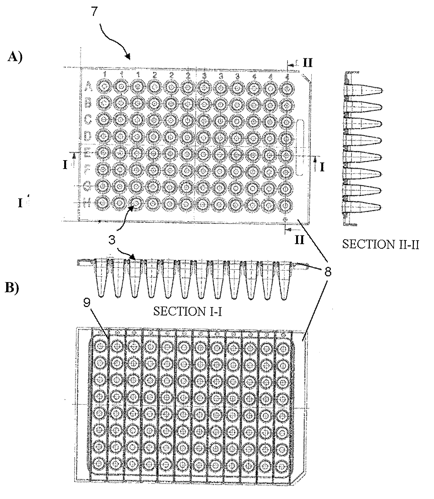
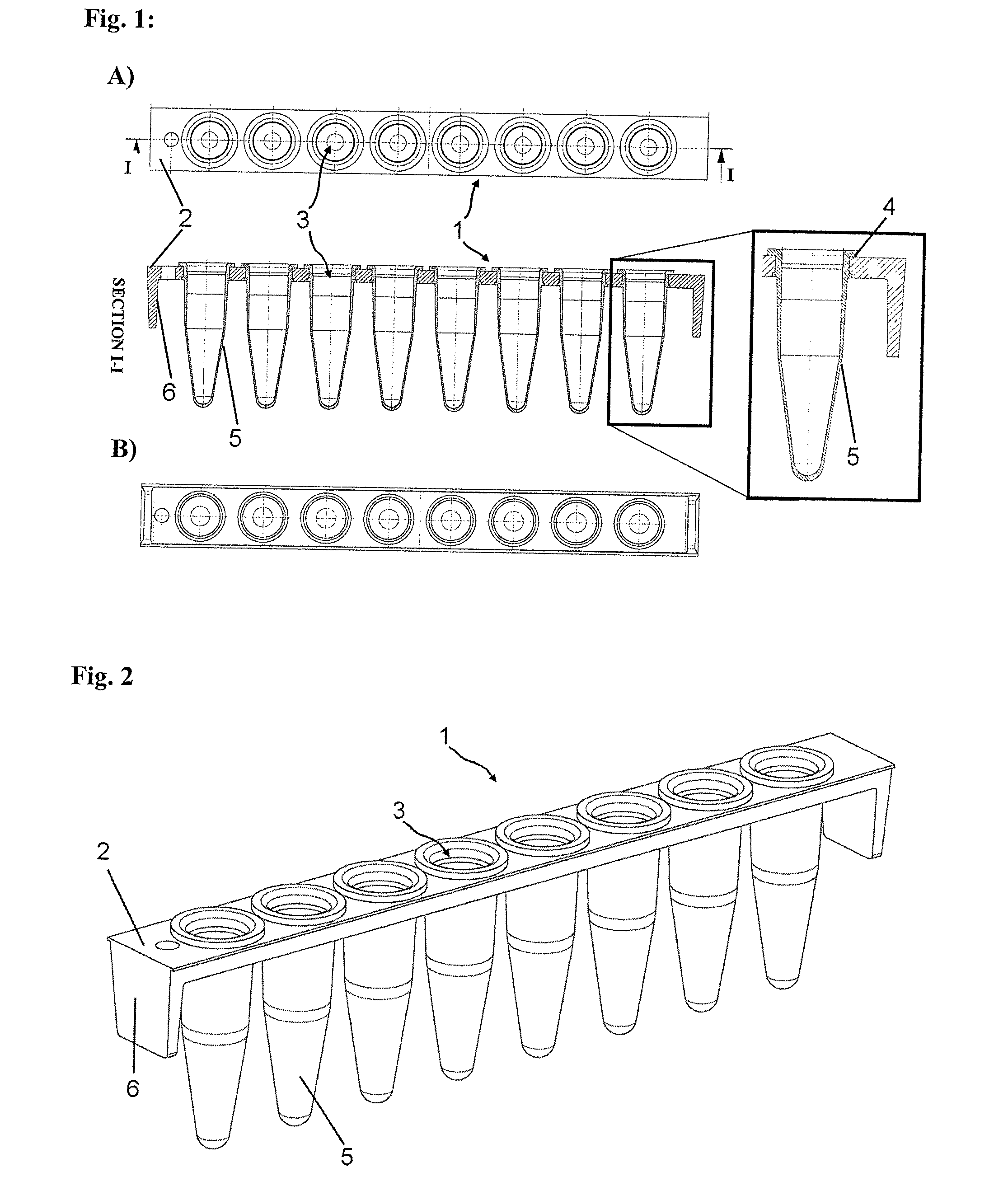
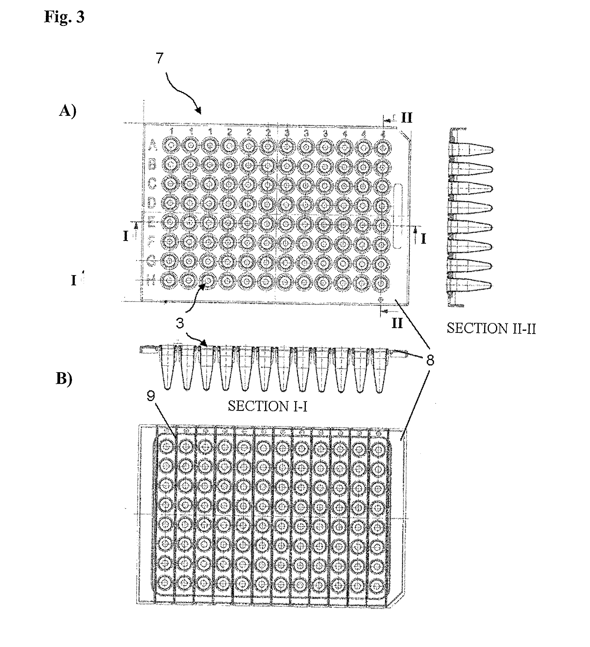
[0004]The present invention now provides a multiwell strip (1) comprising:[0005]a frame portion (2) consisting of a first material;[0006]a plurality of wells (3) consisting of a second material;

wherein the frame portion (2) has an essentially planar top surface having a plurality of holes extending through said top surface arranged in a line; wherein the wells (3) extend downwardly through the plurality of holes in the frame portion (2)and are joined with the top surface of the frame portion (2) so that the receiving portions (5) of the wells (3) are beneath the top surface; and wherein the first material and the second material are different and the first material is stiffer than the second material.

[0007]By “stiffer” in context of the present invention it is meant that the frame portion (2) confers the strip a rigidity, strength and straightness required for easy handling and robotic manipulation. However, the wells (3) in which the samples are placed have other desired properties...


PUM

PropertyMeasurementUnit
thicknessaaaaaaaaaa
temperatureaaaaaaaaaa

Abstract

The present invention relates to a multiwell strip comprising a frame portion consisting of a first stiff material, and a plurality of wells arranged in a line and consisting of a second material, which is not as stiff as the first material. Furthermore, the present invention relates to a multiwell-frame for obtaining a multiwell strip according to the present invention and methods for producing a multiwell strip according to the present invention.

Description

TECHNICAL FIELD[0001]The present invention relates to multiwell strips. In particular the invention relates to multiwell strips consisting of two materials.BACKGROUND OF THE INVENTION[0002]Molecular biological research and clinical diagnostic procedures and techniques require wells and tubes with small volumes for qualitative and quantitative assays and / or for sample storage and retrieval. Furthermore, in order to handle multiple samples at a time prior art devices provide so called multiwell strips with eight wells arranged in a line (e.g. U.S. D445,907 S). These multiwell strips commonly consist of material which has to be chosen for its ability for thermal transfer and resistance. Prior art devices commonly consist of polypropylenes (PP). However, PP is of low stiffness and prone to heat distortion. Thus, prior art multiwell strips are difficult to handle and not suited for automated procedures recruiting robotics.[0003]Thus, there is a need for multiwell strips providing both, w...

Claims


Application Information

Patent Timeline
Patent Type & Authority Applications(United States)
IPC IPC(8): C12Q1/00B29C45/12C12Q1/02B01L3/00C12Q1/68G01N33/566
CPCB01L3/50851B01L3/50855B01L2200/12B29C45/16B01L2300/0829B01L2300/0858B01L2300/021
Inventor DAY, PAULCOLLINS, PETERLERNBECHER, THOMAS
Owner 4TITUDE
Why Eureka
Try Eureka