Semantic Zoom within a Diagram of a System

a system and system technology, applied in the field of diagrams, can solve problems such as difficulty for a system designer or user to fully understand, and achieve the effect of facilitating faster input and faster zooming

Active Publication Date: 2013-01-31
NATIONAL INSTRUMENTS
View PDF1 Cites 73 Cited by
  • Summary
  • Abstract
  • Description
  • Claims
  • Application Information

AI Technical Summary

Benefits of technology

[0011]Where the user input is received in a continuous manner, the diagram may also be updated continuously. For example, as the user begins to provide the user input, the diagram may be updated, e.g., based on the user's input. As the user continues to provide the input, the diagram may be continuously updated, e.g., until the user ceases to provide the input. In some embodiments, the rate at which the zoom is performed may depend on the rate at which the user provides the input. For example, the zoom may be performed more quickly as the user provides the input more quickly. As a specific example, the user may provide at least a portion of the input using a scroll wheel of a mouse; as the user scrolls faster or slower, the zoom may be performed (e.g., via a plurality of updates to the diagram) faster or slower, respectively. In some embodiments, this effect may appear as a “fish eye lens” effect, e.g., changing from a normal lens view to a fish eye lens view as the zoom occurs.

Problems solved by technology

Accordingly, it is difficult for a designer or user of a system to fully understand all of hardware, physical interconnections, software, and software interconnections of the system in an intuitive manner.

Method used


Image

  • Semantic Zoom within a Diagram of a System
  • Semantic Zoom within a Diagram of a System
  • Semantic Zoom within a Diagram of a System

Examples


Embodiment Construction

Incorporation by Reference

[0026]The following references are hereby incorporated by reference in their entirety as though fully and completely set forth herein:

[0027]U.S. Pat. No. 4,914,568 titled “Graphical System for Modeling a Process and Associated Method,” issued on Apr. 3, 1990.

[0028]U.S. Pat. No. 5,481,741 titled “Method and Apparatus for Providing Attribute Nodes in a Graphical Data Flow Environment”.

[0029]U.S. Pat. No. 6,173,438 titled “Embedded Graphical Programming System” filed Aug. 18, 1997.

[0030]U.S. Pat. No. 6,219,628 titled “System and Method for Configuring an Instrument to Perform Measurement Functions Utilizing Conversion of Graphical Programs into Hardware Implementations,” filed Aug. 18, 1997.

[0031]U.S. Pat. No. 7,042,469, titled “Multiple Views for a Measurement System Diagram,” filed Dec. 23, 2002.

[0032]U.S. Patent Application Publication No. 2001 / 0020291 (Ser. No. 09 / 745,023) titled “System and Method for Programmatically Generating a Graphical Program in Res...


PUM


Abstract

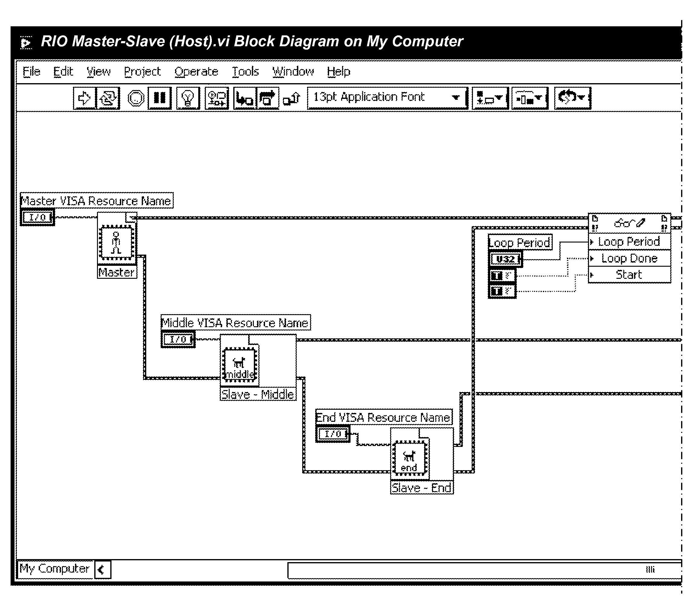
Providing zooming within a system diagram. Initially, a diagram of a system may be displayed. The diagram may include a plurality of icons representing physical components of the system. These plurality of icons may be initially displayed at a first level of magnification. User input to zoom on a first physical component in the diagram may be received. Accordingly, the first physical component may be displayed at a second level of magnification and other ones of the physical components may be displayed at a third level of magnification. The second level of magnification may be greater than the first level of magnification and the third level of magnification may be less than the first level of magnification. Alternatively, or additionally, different representations for various components of the system may be displayed in the diagram during or after the zoom.

Description

FIELD OF THE INVENTION[0001]The present invention relates to the field of diagrams, and more particularly to a system and method for providing zooming within a diagram of a system.DESCRIPTION OF THE RELATED ART[0002]Currently, many engineers design and use systems involving many different devices. Additionally, these different devices typically run or are configured according to disparate software programs that are deployed on or among the multiple different devices. Accordingly, it is difficult for a designer or user of a system to fully understand all of hardware, physical interconnections, software, and software interconnections of the system in an intuitive manner. Thus, improvements in understanding and designing systems are desired.SUMMARY OF THE INVENTION[0003]Various embodiments of a system and method for providing zooming within a diagram of a system.[0004]Initially, a diagram of a system may be displayed. The diagram may include a plurality of interconnected icons represen...

Claims


Application Information

Patent Timeline
Patent Type & Authority Applications(United States)
IPC IPC(8): G06F3/048
CPCG06F3/041G06F3/04817G06F3/04883G06F2203/04806
Inventor KODOSKY, JEFFREY L.FULLER, III, DAVID W.CORRELL, JEFFREY N.SHAH, MOHAMMED KAMRANKORNERUP, JACOBHAYLES, TIMOTHY J.GABBERT, ADAM K.CIFRA, CHRISTOPHER G.LOY, JENIFER M.POSTMA, SCOTT D.ASHBY, RICHARD M.CRAIN, II, CHARLES E.
Owner NATIONAL INSTRUMENTS
Why Eureka
Try Eureka