Scissor linkage mechanism

Inactive Publication Date: 2013-02-07
WEBER KNAPP
View PDF4 Cites 16 Cited by
  • Summary
  • Abstract
  • Description
  • Claims
  • Application Information

AI Technical Summary

Benefits of technology

The present invention is a mounting apparatus for objects that allows for customization of position without unnecessary orientations. The apparatus has a low cost and minimal number of components and maintains the desired position.

Problems solved by technology

A variety of complex, heavy and expensive devices have been created to provide desired mounting features, e.g., providing multiple degrees of freedom for movement while securely retaining a heavy object.
A benefit as well as a drawback of such devices is that the degrees of freedom are not limited.
In other words, the flat screen device may be moved and position in orientations that are entirely impractical, e.g., directed fully away from a useable viewing angle.
Heretofore, tradeoffs between cost and performance were required.

Method used


Image

  • Scissor linkage mechanism
  • Scissor linkage mechanism
  • Scissor linkage mechanism

Examples


first embodiment

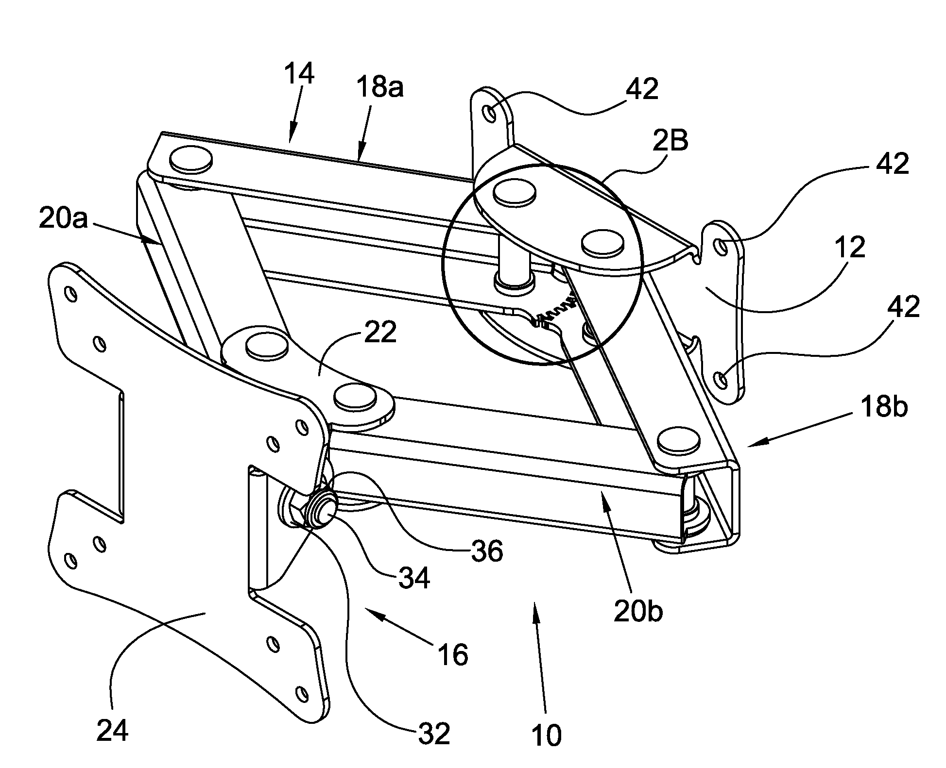
[0064]A first embodiment is shown in FIGS. 3A-4E wherein swivel assembly 16 may be moved inwardly and outwardly in the directions represented by bi-directional arrow 46, may pivot, or more particularly rotate and translate, side to side about arcuate bi-directional arrow 48 located proximate swivel assembly 16, and may pivot upwardly and downwardly about axis 50. Such degrees of freedom are provided by the arrangement of links 18a, 18b, 20a and 20b.

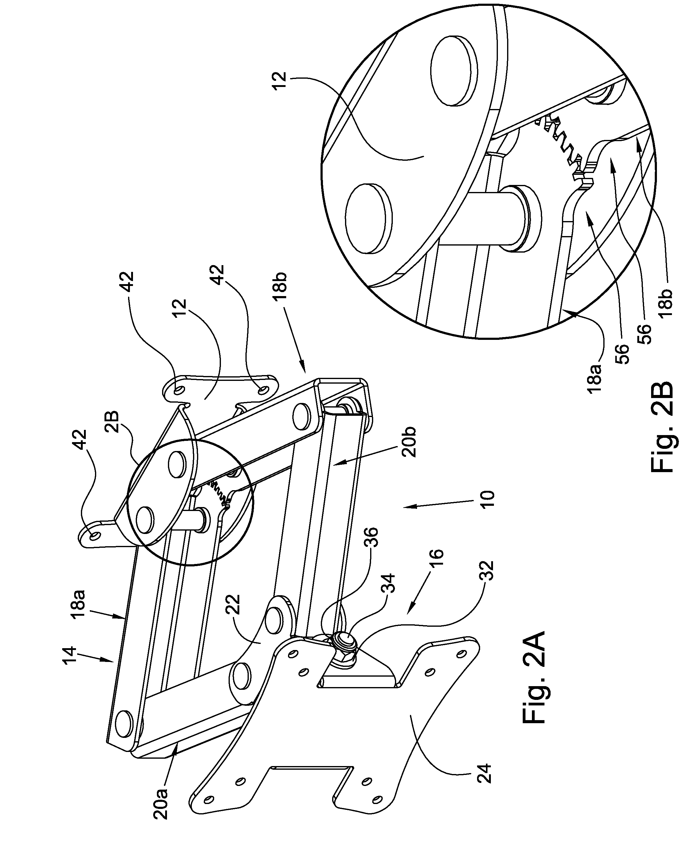
[0065]Links 18a and 18b each include spaced apart parallel side walls 52a and 52b. At a first end of each of links 18a and 18b, i.e., end 54, each of links 18a and 18b includes geared portion 56. Geared portion 56 may comprise gears 58a and 58b on space apart parallel side walls 52a and 52b, respectively. Alternatively, geared portion 56 may comprise a gear 58a on one of side walls 52a in combination with a gear 58b on one of side walls 52b. Geared portion 56 further comprises through holes 60a and 60b disposed in side walls 52a and 52b,...

second embodiment

[0070]A second embodiment is shown in FIGS. 5A-5E wherein swivel assembly 16 may be moved inwardly and outwardly in the directions represented by bi-directional arrow 104, may pivot, or more particularly rotate and translate, side to side about arcuate bi-directional arrow 106 located proximate swivel assembly 16, and may pivot upwardly and downwardly about axis 108. Such degrees of freedom are provided by the arrangement of links 18a, 18b, 20a and 20b.

[0071]As shown in the second embodiment, through holes 74a and 74b of link 20a are in registered alignment with through holes 86a and 86b, while through holes 74a and 74b of link 20b are in registered alignment with through holes 88a and 88b. Similarly, through holes 80a and 80b of link 20a are in registered alignment with through holes 66a and 66b of link 18a, while through holes 80a and 80b of link 20b are in registered alignment with through holes 66a and 66b of link 18b. Lastly, through holes 60a and 60b of link 18a are in regist...

third embodiment

[0073]A third embodiment is shown in FIGS. 6A-6C wherein swivel assembly 16 may be moved inwardly and outwardly in the directions represented by bi-directional arrow 110 and may pivot upwardly and downwardly about axis 112. Such degrees of freedom are provided by the arrangement of links 18a, 18b, 18c and 18d. It should be appreciated that links 18c and 18d are identical in arrangement to links 18a and 18b; however, as shown in FIGS. 6A-6C, the distance between spaced apart parallel side walls 52a and 52b of links 18c and 18d is slightly smaller than the distance between spaced apart parallel side walls 52a and 52b of links 18a and 18b so that links 18c and 18d are permitted to fit within links 18a and 18b.

[0074]As shown in the third embodiment, through holes 60a and 60b of link 18a are in registered alignment with through holes 86a and 86b, while through holes 60a and 60b of link 18b are in registered alignment with through holes 88a and 88b. Similarly, through holes 66a and 66b o...


PUM


Abstract

A mounting apparatus for an object including a rear mounting plate, a linkage system having first, second, third and fourth links, each of the first, second, third and fourth links includes first and second ends, and a swivel assembly. The first end of each of the first and second links is pivotably secured to the rear mounting plate, the second end of each of the third and fourth links is pivotably secured to the swivel assembly, the second end of the first link is pivotably secured to the first end of the third link, and the second end of the second link is pivotably secured to the first end of the fourth link. The linkage system includes a first gear and a second gear, and the first gear is rotatably connected to the second gear.

Description

FIELD OF THE INVENTION[0001]The invention broadly relates to scissor linkage mechanisms, more specifically to a scissor linkage mechanism for supporting an object such as a flat screen, and even more particularly to a scissor linkage mechanism for supporting an object which provides at least one of the following modifiable orientations: inward and outward movement of the object; side to side movement of the object; and, upward and downward tilting of the object.BACKGROUND OF THE INVENTION[0002]Flat screen devices, such as televisions, computer monitors, touch screens, etc., have become common in a variety of settings. For example, flat screen televisions are often secured on a wall via a moveable mount, while flat screen computer monitors are secured to a desk via a similar moveable mount. An advantage of the foregoing flat screen devices is the low profile or thickness of these devices which permits a minimization of the space consumed by using and / or storing the device. For exampl...

Claims


Application Information

Patent Timeline
IPC IPC(8): F16M13/02
CPCF16M11/10F16M11/2014F16M11/2092F16M2200/068F16M2200/061F16M11/2085F16M11/22F16M13/02
Inventor BELL, MATTHEW A.
Owner WEBER KNAPP
Why Eureka
Try Eureka